


5
UVS33/36 Vent-Free Heaters
20002211
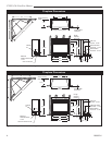
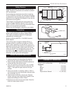
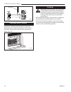
Clearance to Combustibles
Top of unit to ceiling ................................. 36" (914 mm)
Front of unit to combustibles ....................36' (914 mm)
Appliance
Top ......................................................... 0" (0 mm)
Bottom ..................................................... 0" (0 mm)
Sides ....................................................... 0" (0 mm)
Back ........................................................ 0" (0 mm)
Perpendicular Sidewall ....................... 6" (152 mm)
Safety Devices
Adequate combustion and ventilation air must be pro-
vided. The flow of combustion and ventilation air MUST
NOT be obstructed.
Provide adequate clearances around the air opening
into the combustion chamber; and adequate accessibili-
ty clearance for servicing and proper operation. NEVER
obstruct the front opening of the heater or cover the top
and bottom louvres (grilles).
These heaters are equipped with a pilot system fea-
turing an Oxygen Depletion Sensor (O.D.S.) shut-off
device. The O.D.S. pilot will shut down the heater when
there is not enough fresh air available.
Report any parts damaged in shipment to your dealer.
Description
The UVS vent-free heaters uses a frame window with
screen mesh that does not use any catalytic filters.
This model is available as Natural or Propane gas,
equipped with a standing pilot.
Design-certified to ANSI Z21.11.2a-2003 Unvented
Room Heaters.
The UVS33 model is shipped at 20,000 BTU/hr. It
includes orifices for operation at 15,000 and 10,000
BTU/hr. When operating at 10,000 BTU/hr, the unit is
approved for bedroom use. Based on the National Fuel
Gas Code and local codes, please match the correct
orfice size and BTU's to corresponding room size. This
conversion must not be completed in the field. Once
final rate is established, remaining orifices are to be
discarded, not left behind with the fireplace.
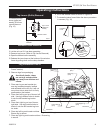
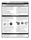
Orifice Conversion Instructions
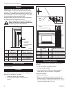
1. Locate burner with tiles, pilot shield and orifice.
2. Unscrew two hex nuts connecting pilot shield to
burner with tiles. Move pilot shield to right. (Fig. 2)
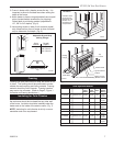
3. Remove sheet metal screws at left and right side of
burner with tiles and remove burner.
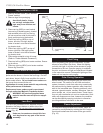
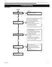
4. Use 7/16" wrench to remove orifice. (Fig. 3) Install
desired orifice in place of orifice just removed. See
Table 3 . Use approved pipe compound for pipe
threads.
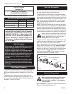
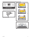
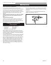
5. Remove air shutter, if necessary (Refer to Table 1),
from burner pan by removing shutter retaining screw
then air shutter. (Fig. 4)
6. Install correct air shutter on burner pan. Replace
shutter retaining screw. Adjust the air shutter to the
appropriate settings as listed in Table 1.
7. Reinstall burner with tiles and pilot shield. Check for
leaks with soapy water solution.
CO103
Gas Conversion
Air shutter
2/15/99 djt
Burner Pan
Air Shutter
Retaining
Screw
Air Shutter
Adjustment
Air Shutter
CO103
Fig. 4 Use appropriate air shutter and adjust according to
Table 1.
Front
View
CO101a
UVS33
Gas Conversion
Manifold
1/19/00 djt
Burner with
Tiles
Pilot
Log Supports
Orifice
CO101a
Fig. 2 Manifold assembly and orifice location.
Hex Nut
Air
Shutter
Pilot Shield
Sheet
Metal Screw
Sheet Metal Screw
Hex
Nut
CO102
UVS33
Orifice
Gas Conversion
1/19/00 djt
Orifice
Fig. 3 Replace orifice.
CO102