


19
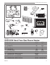
UVS33/36 Vent-Free Heaters
20002211
Fan Kits
FK12 Fan Kit
This auxiliary fan system increases the efficiency of the
circulation of the heating air. The FK12 Fan Assembly is
a fixed speed fan system and does not allow for vari
-
able speed control. It does not use the speed control
unit or the heat sensor used in the FK24 kit.
Specifications
115 Volts / 60 Hz / .75 Amps.
Installation
The fan assembly is supplied fully wired eliminating the
need for a licensed electrician to carry out the installa-
tion.
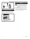
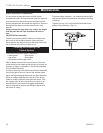
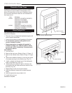
1. Open the lower louvre assembly. Maneuver the fan
& bracket assembly around the gas valve and lines
to locate the unit against the back wall of the appli-
ance, resting on the base.
2. With the protective cover removed from the self-ad
-
hesive 'Velcro' strips apply mild pressure to the fan &
bracket unit to secure the strips to the metal panels.
No further securing is required.
3. Power to the fan can be supplied by plugging the
supply lead into a conveniently located wall socket
or by using a hard-wired EB-1 connector box.
FK24 Fan Kit
This auxiliary fan system increases the efficiency of the
circulation of the heating air.
The FK24 fan kit allows variable speed control of the
circulation fan and also incorporates a heat sensor in
the circuit.
Specifications
115 Volt / 60Hz / .75 Amps
Installation
The fan assembly and other components are supplied
fully wired eliminating the need for a licensed electrician
to carry out the installation.
If hard wiring the fan in using Method B (following) we
strongly recommend the use of a licensed electrician.
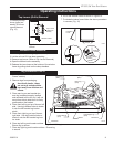
1. Open the lower louvre assembly. Maneuver the fan
& bracket assembly around the gas valve and lines
to locate the unit onto the screw studs on the back of
the fireplace.
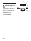
2. Install the thermal sensor under the bottom of the
firebox, locating it over the two 10 mm studs and
secure it with nuts.
Optional Accessories
3. Locate the fan speed control unit. This can be fitted
behind the lower louvre assembly or located
remotely in a conveniently located wall mounted
electrical box. Remote location of the
speed control will require suitable extension of the
component wiring.
4. The power supply may be connected in two ways:
Method A
Route the 6’ lead fitted to the unit to a conveniently
located wall socket.
Method B
The EB-1 receptacle box (Pt. # ZA1200) may be
hard wired into the house supply. The fan lead is
then plugged into the EB-1 box
Electrical Connection
The EB-1 electrical junction box is available for use with
the fan kits.
Remote Controls
Optional remote control units are available to control
different functions of the appliance.
Model Function(s) Controlled
RC1 ON/OFF
RC2 ON/OFF and Temperature
IMTFK Wall mounted thermostat control
Outside Air Termination
The AK-1 completes the connection from outside air kit
to out-of-doors. (Does not include 4" flex duct.)
Ceramic Brick Liner
Ceramic panels are available to line the firebox area.
Model 33BDVCR
Decorative Bay Screen Kit
The 33BSTK Bay Window Screen Kit is available to
place on the front of the unit.