


11
Vermont Castings Radiance Vent-Free Gas Heater
20004555
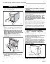
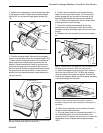
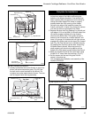
4. Attach the fan assembly to the fan bracket provided
in the log box. Use #10 sheet metal screws provided
with fan kit. Do not remove finger guard screws.(Fig.
10)
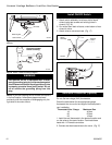
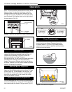
5. Connect snapstat leads. Disconnect the snapstat
module from the leads inside the snapstat bracket. (Fig.
11) Bend open the snapstat bracket. Use needlenose
pliers to remove the black plastic grommet from the
bracket. Discard the bracket. Insert the grommet and
wires into the large hole at the bottom right corner of
the inner shroud. Feed the snapstat wire leads through
the grommet into the stove interior. Connect the two
wires to the two snapstat extension leads attached to
the inner shroud.
Snapstat Bracket
Snapstat Module
Pinch
Grommet to
Remove
ST670
Fig. 11 Remove the snapstat and grommet from the bracket
and insert the grommet into the inner shroud.
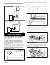
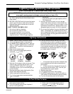
6. Position the fan assembly so the ducts slide be-
tween the inner and outer shroud. The inner shroud
should engage with the two slots in the ends of the
bracket so that bracket and shroud are interlocked.
(Fig. 12) Secure the bracket with the four sheet metal
screws provided in the finish bag.
7. Route the rheostat wire assembly to the right
between the inner and outer shroud. Run the wire
through the slots at the bottom right corner of the inner
shroud.
8. Refasten the outer shroud to the inner duct assem-
bly.
{Inner Shroud}
Fig. 12 Position the fan to engage the inner shroud with the
fan bracket slots and secure with sheet metal screws.
Outer
Shroud
Slot
Slot
ST194
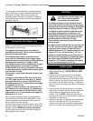
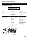
9. Install the snapstat by loosening the front screw on
the inner side of the duct (Fig. 13) slide the snapstat
under the head of the screw and tighten. Connect the
leads to the snapstat. Make sure the snapstat assembly
is mounted straight front to back.
10. Slide shroud assembly over the sides and fasten
the four screws loosened earlier.
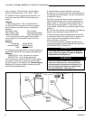
11. Plug the power cord into a standard grounded 110
volt household outlet. If the fan control knob is not
turned to the OFF position, the fan will turn on when the
temperature at the snapstat reaches approximately
109°F.
Fig. 13 Install the snapstat and connect the extension wire
terminals. View is with top removed, however, access is
available through the rear when installing fan before gas line
connection.
Snapstat
Left Air Duct
ST671
Fig. 10 Attach the fan assembly to the fan bracket.
Fan
Bracket
Finger Guard
Snapstat
Wire
Rheostat
Wire
ST669