Document #679-800-001 Page 4 of 4 Rev. 1.1, Jan 9, 2006
CM-S1
N.O. VIO
N.C. BLU
COM YEL
BLK
RED
12/24V
GND
SPDT
Alarm
relay
CM-S1
N.O. VIO
N.C. BLU
COM YEL
BLK
RED
12/24V
GND
SPDT
Alarm
relay
UL
LISTED
12VDC
ALARM
UL LISTED
12VDC
POWER SUPPLY
POWER
N.O. initiating
circuit
12/24V GND
Battery-backed 12 or 24
VDC Power Supply. Fuse
or current limit at 0.5 A for
each CM-S1
UL Listed Alarm Control Panel
CM-S1
N.O. VIO
N.C. BLU
COM YEL
BLK
RED
12/24V
GND
SPDT
Alarm
relay
CM-S1
N.O. VIO
N.C. BLU
COM YEL
BLK
RED
12/24V
GND
SPDT
Alarm
relay
E.O.L.R.
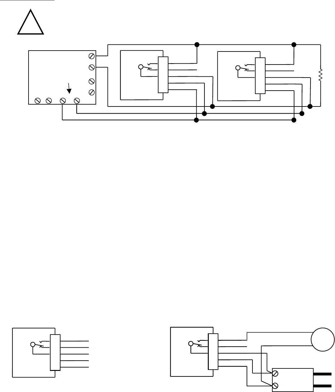
WIRING DIAGRAMS
ENSURE POWER IS OFF WHEN CONNECTING THE PIGTAIL CABLE TO THE CM-S1
TYPICAL CONNECTION OF TWO CM-S1's TO AN ALARM CONTROL PANEL
1. The CM-S1 is for use with UL Listed Alarm Control Panels (Fire or Fire/Burglar type or Critical Process Management Equipment)
that have 12 to 24 VDC alarm initiating circuits.
2. The Alarm Control Panel (Fire or Fire/Burglar type or Critical Process Management Equipment) must be dedicated to CO detection or
have alarm devices that provide a distinctive alarm for carbon monoxide detection. Do not connect the CM-S1 to Fire Alarm Circuits.
3. The CM-S1 is intended for installation in buildings in non-hazardous locations such as residences, retail stores, office buildings and
institutional buildings.
4. The CM-S1 is NOT intended for use in industrial applications such as refineries, chemical plants, etc. The CM-S1 is NOT intended
for use in parking garages, as the controller for exhaust systems.
5. LOCATION: Place the unit at a level where people breathe: about 5 feet (1.5 meters) above the floor. Mount the CM-S1 in a vertical
position on a wall or column. Do NOT mount the CM-S1 in a corner.
6. SPACING: Use the same spacing as for smoke detectors – 30 foot (9 meters) centers, 900 sq. feet (83 sq. meters) per detector.
7. INSTALLATION: See page 1.
8. The alarm control panel zone inputs must be terminated with end of line resistors (E.O.L.R.), which are provided with the panel.
9. When using the CM-S1 with normally closed initiating circuits, use the "N.C." and "COM" alarm relay connections.
The CM-S1 has not been evaluated as a stand-alone unit by U.L.
larm Relay: SPDT,
1.0 Amps., 60VDC, 60 VA
dry contacts, no polarity
UL Listed Class 2
Power Source:
12-24 VDC, 1 VA
!
CM-S1 CONTROLLING A REMOTE ALARM


