Document #679-800-001 Page 1 of 4 Rev. 1.1, Jan 9, 2006
MACURCO GAS DETECTORS CM-S1 INSTALLATION AND
OPERATION INSTRUCTIONS
GENERAL INFORMATION
The CM-S1 is a low voltage (12-24 VDC) all electronic detector of Carbon Monoxide (CO). The CM–S1 is designed for connection to UL Listed
alarm control panels (Fire or Fire/Burglar or Critical Process Management Equipment). NOTE: Any time the words “Control Panel” or “Alarm
Panel” or “Alarm Control Panel” are used in these instructions, what is meant is a UL Listed Fire or Fire/Burglar or Critical Process Management
Equipment. Alarm control panels that work on 12 or 24 VDC can provide battery backup to the CM-S1 detectors. This carbon monoxide detector is
designed to detect CO gas from ANY source of combustion. It is NOT designed to detect smoke, fire or any other gas.
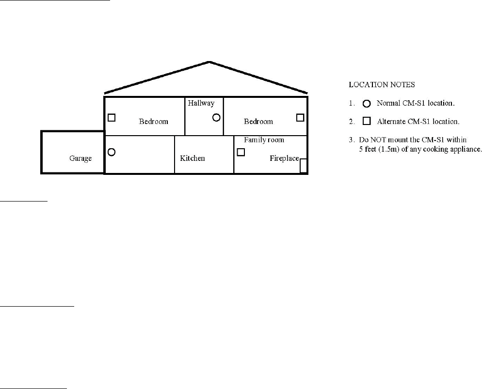
LOCATION
There are two usual sources of CO in homes -- defective heat sources (furnaces or wood burning stoves) and automobiles running in adjoining
garages. The CM-S1 can provide protection from these sources, as well as any other sources of CO.
For best protection, mount a CM-S1 in the hallway near each bedroom area. In addition, another CM-S1 may be mounted just inside the door from
the adjoining garage. Consider placing another detector in a bedroom that is adjacent to a furnace room.
Do NOT mount the unit in the garage. Do NOT mount the CM-S1 where the normal ambient temperature is below 40° F (4.4° C) or exceeds 100° F
(37.8° C), or within 5 feet (1.5 meters) of a cooking appliance.
SPECIFICATIONS
Voltage: 12-24 VDC Current (standby/alarm @ 12-24V): 20mA/40mA (250 mA peak for 14ms/sec)
Size: 3 1/8” x 5 1/8” x 1 ½” Power (standby/alarm @ 12V): ¼ Watt / ½ Watt
Shipping Weight (each): One pound Power (standby/alarm @ 24V): ½ Watt / 1 Watt
Alarm Relay: SPDT, 1 Amp, 60 VDC, 60 VA Operating Temperature Range: 32° to 120° F
Alarm Setting: Per UL 2034 Buzzer Rating: 85 dBA at 10 Feet
Color: White
INSTALLATION
See wiring diagram on page 4 for information on connections of the CM-S1. Macurco recommends a minimum of 22 AWG wire for runs up to 200
ft., and 18 AWG wire for longer runs.
Mount the CM-S1 at the height that people breath: 4 to 5 feet (1.2 to 1.5 meters) above the floor. The unit can be placed vertically or horizontally on
a wall, so the information on the front of the CM-S1 can be read in a normal manner. The word UP and a directional arrow on the internal cover
indicate the correct mounting orientation of the detector.
A rear housing enclosure is included with the CM-S1 faceplate. This enclosure configuration allows the unit to mount-flush on a wall. Wiring is
routed through an access area on the base of the rear housing. A thin mid-plate enclosure component is also supplied with the CM-S1. This mid-
plate component is used to mount the CM-S1 on a 2 x 4 single-gang, or “handy” electrical box, provided by the installer. The CM-S1’s faceplate
component (with the detector attached) is then mounted on the mid-plate component. Electrical connections to the CM-S1 are made via the supplied
five-conductor pigtail cable. The pigtail cable is first connected to the control panel wiring by means of wire nuts (refer to wiring diagram on page 4
for proper pigtail wiring). The pigtail cable’s connector then snaps into the mating connector on the back of the CM-S1 PCA, allowing easy
installation and replacement of it. For proper detector operation, ensure that the CM-S1 is connected to a continuous source of power (not controlled
by a wall switch). The CM-S1 power consumption figures represent worst-case conditions and will vary as the applied DC voltage varies.
The alarm relay of the CM-S1 is a dry contact and rated at 1 Amp, 60 VDC, 60 VA. It is not suitable for fan control use. When connecting the units
to remote buzzers or other devices (all buzzers or "other devices" must be UL approved), make sure that the load does not exceed the relay’s rating.
External buzzers must be capable of generating a sound output greater than 85 dBA at 10 ft.


