


10
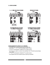
W Y G B O RC RH C
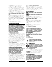
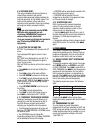
2 WIRE, 24 VOLT AND MILLIVOLT HEAT ONLY SYSTEMS
24 VOLT
HEAT
TRANSFORMER
120 VAC
HEAT
SYSTEM COMMON
OPTIONAL
RC-RH
JUMPER PROVIDED
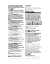
W Y G B O RC RH C
3 WIRE HEATING SYSTEM (3RD WIRE FOR FAN)
24 VOLT
HEAT
TRANSFORMER
120 VAC
FANHEAT
SYSTEM COMMON
OPTIONAL
RC-RH
JUMPER PROVIDED
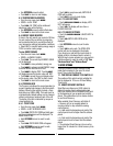
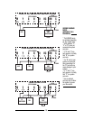
W Y G B O RC RH C
3 WIRE COOLING SYSTEM
24 VOLT
COOL
TRANSFORMER
120 VAC
AC
COMPRESSOR
FAN
SYSTEM COMMON
OPTIONAL
RC-RH
JUMPER PROVIDED
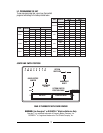
WIRING DIAGRAM
NOTES
(APPLIES TO ALL
DRAWINGS)
* The DASHED wires
are optional depending
on your system type.
* Verify whether “C”,
“X” or “B” wires are
connected to system
common.
* If “B” and “O” are
both present, it is likely
that “B” is a system
common.
* If a “B” wire in your
system is a common,
then connecting it to
the “B” terminal may
cause damage to your
system.
* If “Y” and “C” are
both present, it is likely
that “C” is a system
common.
* Use an optional
common wire to allow
the system to power
your thermostat.