


2© COPYRIGHT 2004 LUX PRODUCTS CORPORATION. ALL RIGHTS RESERVED
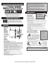
ATTACHING WIRES
CAUTION
Do not allow wires to touch each other or parts on thermostat. Wires must be trapped between
black spacer and brass terminal. Also, be sure to securely tighten all 7 electrical terminal screws.
NOTE
If you are mounting the base to
a soft material like plasterboard
or if you are using the old
mounting holes, the screws
may not hold. Drill a 3/16-in.
(4.8mm) hole at each screw
location, and insert the plastic
anchors provided. Then mount
the base as described below.
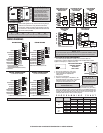
WIRING DIAGRAMS
GYWRCRHOB
Latch Button
Base
Terminals
4. Hold the base against the wall, with the wires coming through
wherever it is convenient for wiring. Route the wires to the
terminal block. Position the base for best appearance (to hide
any marks from an old thermostat). Attach the base to the wall
with the two screws provided.
These diagrams below are provided for new installations or unreferenced wires.
GYWRCRHOB
FAN RELAY
COOLING COMPRESSOR
HEATING CONTROL
COOL TRANSFER
HEATING TRANSFER
DAMPER OR CHANGEOVER
VALVE (Powered in Cool)
DAMPER OR CHANGEOVER
VALVE (Powered in Heat)
If replacing a Honeywell TM-11, tape off wire "R";
connect wire "B" to terminal "RH".
RCR RH
G F
4 H W
5 V
TC
TAPE OFF
HEATING SYSTEMS
GYWRCRHOB
FAN RELAY
COOLING COMPRESSOR
HEATING CONTROL
COOL TRANSFER
HEATING TRANSFER
DAMPER OR CHANGEOVER
VALVE (Powered in Cool)
DAMPER OR CHANGEOVER
VALVE (Powered in Heat)
RC
G F
C Y
V R
TC
TAPE OFF
COOLING SYSTEMS
*
B
TAPE OFF
*
*
If both "Y" and "C" wire are present, tape off "C" wire.
If both "Y" and "C" wire are present, tape off "C" wire. If both "Y" and "C" wire are present, tape off "C" wire.
4- or 5-WIRE WITH ONE TRANSFORMER 5- or 6-WIRE WITH TWO TRANSFORMERS
*
If replacing a Honeywell thermostat with a clock wire "C",
tape off wire "C".
**
C
TAPE OFF
**
GYWRCRHOB
FAN RELAY
COOLING COMPRESSOR
HEATING CONTROL
COOL TRANSFER
HEATING TRANSFER
DAMPER OR CHANGEOVER
VALVE (Powered in Cool)
DAMPER OR CHANGEOVER
VALVE (Powered in Heat)
TC
F G
W
TAPE OFF
OPTIONAL
OPTIONAL
HEATING / COOLING SYSTEMS
GYWRCRHOB
FAN RELAY
COOLING COMPRESSOR
HEATING CONTROL
COOL TRANSFER
HEATING TRANSFER
DAMPER OR CHANGEOVER
VALVE (Powered in Cool)
DAMPER OR CHANGEOVER
VALVE (Powered in Heat)
RC
V R
HEATING / COOLING SYSTEMS
Y C
*
**
O
B
TC
F G
W
TAPE OFF
OPTIONAL
OPTIONAL
RH
4 A
RC
V R
C Y
*
O
B
*
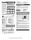
1. Remove fresh batteries from their carton.
2. Cup and hold thermostat body and left tab
in place with left hand. Separarte tabs
with right hand.
3. Remove the used batteries.
4.
Install two new Energizer
®
or DURACELL
®
"AA"
size alkaline batteries in the battery compartment.
Observe the polarity marking shown in the
compartment. Place body back on wall.
5. Align the top of the body onto
the base and press together.
Installation is now complete. Be sure to turn the power back on to your heating
and /or air conditioning system. If this is the first time you are installing batteries, the
thermostat will display “SUN 12:00 AM”. Within 90 seconds the thermostat will begin
to display the room temperature alternately with the time. To correct the display, see
“Setting the TIME and DAY,” after you set the programs.
NOTE
If you have an electric system and the blower does not operate after installation, find the
electric/gas heat jumper on the back of the body. Move the jumper to the ELEC position.
REPLACE BATTERIES WHEN
INDICATOR APPEARS
OR AT LEAST
ONCE A YEAR.
INSTALLING BATTERIES/ MAINTENANCE
The TX250 requires batteries to operate your furnace and retain its
programming in memory. Replace the batteries when the REPLACE indicator
appears in the display or at least once a year.
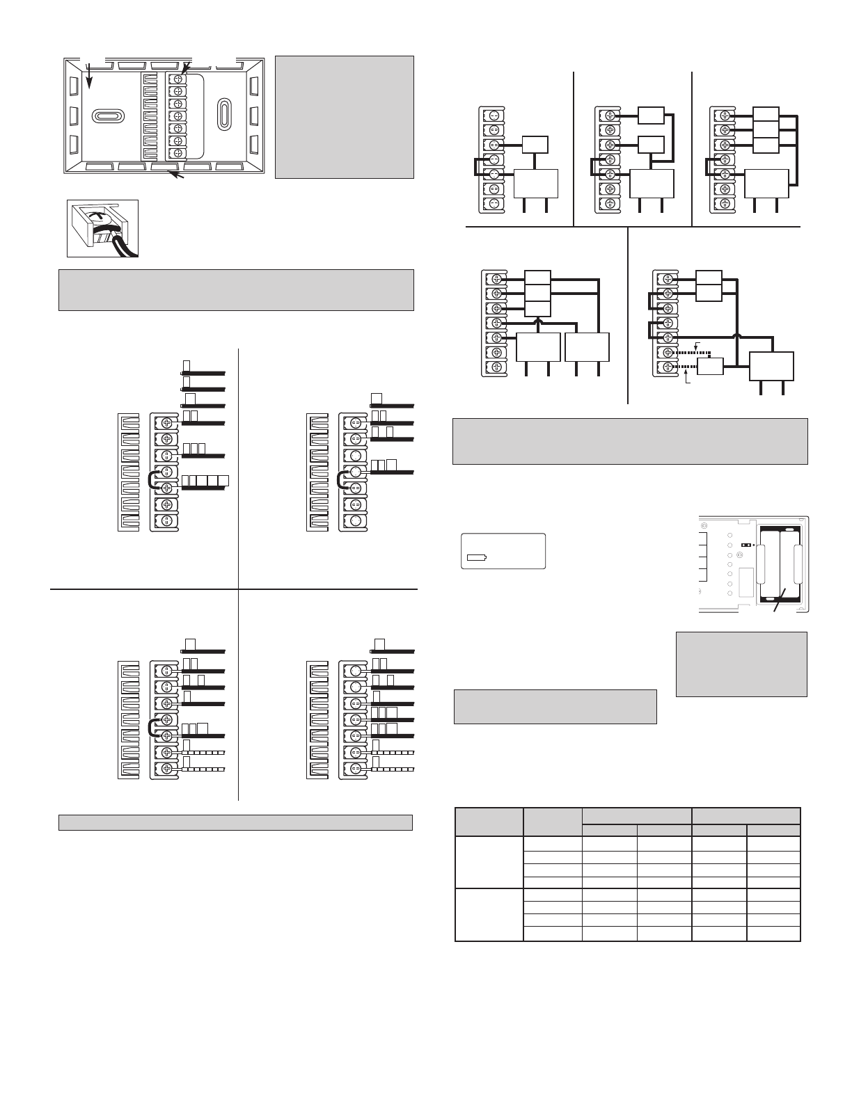
PROGRAMMING CHART
LO BAT
GAS
ELEC
IN
H
R
O
SE
"AA"
"AA"
Battery
Compartment
NOTE
When replacing batteries, you
have approximately 1 minute
before programs are lost.
TYPICAL HOOKUP FOR 2-WIRE
24V HEATING SYSTEM AND
MILLIVOLT SYSTEM
24 VAC
TRANSFORMER
OR
THERMOPILE
GAS
VALVE
110
TYPICAL HOOKUP FOR 3-WIRE
HEAT SYSTEM IF THIRD
WIRE IS FAN WIRE
24 VAC
TRANSFORMER
GAS
VALVE
FAN
110
TYPICAL COOLING AND
HEATING SYSTEM
(4-WIRE)
24 VAC
HEAT
TRANSFORMER
GAS
VALVE
FAN
110
COOL
COMP
TYPICAL COOLING AND
HEATING SYSTEM
(5-WIRE)
24 VAC
HEAT
TRANSFORMER
24 VAC
COOL
TRANSFORMER
REMOVE JUMPER BETWEEN "RC" AND "RH"
GAS
VALVE
FAN
110 110
COOL
COMP
TYPICAL SINGLE-STAGE
HEAT PUMP WIRING
ADD JUMPER BETWEEN "Y" AND "W"
ALTERNATE
FAN
COMP
CHANGE
OVER
24 VAC
HEAT
TRANSFORMER
110
ALTERNATE
GYWRCRHOB
GYWRCRHOB
GYWRCRHOB
GYWRCRHOB
GYWRCRHOB
DAY PERIOD HEAT COOL
TIME TEMP. TIME TEMP.
MON. MORN
THRU DAY
FRI. EVE
NIGHT
MORN
SAT. DAY
and EVE
SUN. NIGHT
WARNING: Use Energizer
®
or DURACELL
®
Alkaline Batteries Only.