


2© COPYRIGHT 2004 LUX PRODUCTS CORPORATION. ALL RIGHTS RESERVED
NOTE
If you are mounting the base to a
soft material like plasterboard or if
you are using the old mounting
holes, the screws may not hold.
Drill a 3/16-in. (4.8mm) hole at
each screw location, and insert the
plastic anchors provided.
Then mount the base as
described below.
GCRW2OBYE
TERMINALS
BASE
TAB
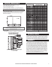
5. Route the wires through the large hole in the base plate by the
terminal block. Hold the base against the wall, with the wires
coming through. Position the base for best appearance (to hide
any marks from an old thermostat). The terminal block should be
either to the right of or below the routing hole. Attach the base to
the wall with the two screws provided.
CAUTION
Read instructions carefully before removing any wiring from existing thermostat. Wires
must be labeled before they are removed. When removing wires from their terminals,
ignore the color of the wires since they may not comply with any standard.
REMOVING THE OLD THERMOSTAT
1. Switch electricity to the furnace and air conditioner OFF; then
proceed with the following steps.
2. Remove cover from old thermostat. Most are snap-on types and
simply pull off. Some have locking screws on the side. These must
be loosened.
3. Note the letters printed near the terminals. Attach labels (enclosed) to each wire
for identification. Label and remove wires one at a time. Make sure the wires do
not fall back inside the wall.
4. Loosen all screws on the old thermostat and remove it from the wall.
MOUNTING THE PSDH121 ON THE WALL
1. Decide whether the thermostat will be mounted vertically or horizontally.
Y
W
CAUTION
Be careful not to drop the unit or disturb electronic parts.
2. Strip insulation 3/8 in. (9.5mm) from wire ends and
clean off any corrosion.
3. Fill wall opening with non-combustible insulation to
prevent drafts from affecting the thermostat.
4. Cup the thermostat with one hand behind the
thermostats display. Separate the unit from its base
plate using the tabs protruding from its body with
the other hand.
Y
W
Y
W
R
ATTACHING WIRES
PLEASE REVIEW THE WIRING DIAGRAMS IN THE NEXT COLUMN
FOR PROPER TERMINAL CONNECTION
CAUTION
Do not allow wires to touch each other or parts on thermostat. Terminated wires must
be trapped between black spacer and brass terminal. Securely tighten all eight electrical
terminal screws.
INSTALLATION OPTIONS
There are four options which are set by a group of numbered jumpers on the
rear of the units circuit board. They are:
J1: The minimum run time jumper J1 sets the minimum length of time that the
thermostat must remain with Heat or Cool either on or off before it will
automatically switch to the alternate On or Off state. This feature prevents short
cycling, and provides compressor protection for cooling units. Choices are 2 or 5
minutes.
J2: The temperature format: jumper selects whether your thermostat displays
temperatures in Celsius or Fahrenheit.
J3: This Jumper determines whether the display will be horizontally or vertically
oriented.
J4: This Jumper controls the “swing” or temperature variation in the home. Using
the smaller number results in more stable temperature, while the wider setting is
provided as a more energy efficient alternative. Users of force hot water systems
may find the 0.25 setting more comfortable.
J3J4 J2 J1
JUMPER POSITIONS
(FOR REFERENCE ONLY
NOT SHOWN TO SCALE)
The table at left is printed on the
circuit board. To change a jumper
position. The closed or shorted
position is that which covers both a
jumpers pins. To prevent its loss, a
jumper may be placed over one pin
only for the open positions. After
settings have been changed, press
the small-unmarked RESET button on the front of the thermostat for the changes
to take effect.
CLOSE
5 min
F
Horizontal
Swing=0.5
OPEN
2 min
C
Vertical
Swing=0.25
J1
J2
J3
J4
INSTALL BATTERIES
For detailed instruction, see BATTERIES/MAINTENANCE to install batteries at
this time.
●
Turn the power back on to your heating and/or air conditioning system.
●
Verify that the system and its fan are operating properly. When set to a high
temperature, the heating system should provide warm air after a short time.
Likewise, a cooling system should provide cool air after a short time. Usually sound
from the furnace and air conditioning units can be heard while they are running.
The rush of moving air should be heard within a short time after either has been
started.
●
The Installation is now complete.
Your thermostat is carefully calibrated at the factory, and will measure
temperature to within ±1°. However, you can adjust the reading of your
thermostat:
●
Slide the MODE switch to OFF.
●
Press and hold the Up and Down buttons until the display shows a single digit
between +5F°(+3C°) and -5F°(-3C°).
●
Then the Up or Down buttons may be used to adjust the reading.
●
The display will return to normal operation after 4 seconds without an
adjustment.
CALIBRATION