


2© COPYRIGHT 2004 LUX PRODUCTS CORPORATION. ALL RIGHTS RESERVED
NOTE
If you are mounting the base to a
soft material like plasterboard or if
you are using the old mounting
holes, the screws may not hold.
Drill a 3/16-in. (4.8mm) hole at
each screw location, and insert the
plastic anchors provided.
Then mount the base as
described below.
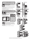
WIRING DIAGRAMS
These diagrams are provided for new installations or un-referenced wires.
GC Y RC O B RH W
TERMINALS
BASE
TAB
5. Route the wires through the large hole in the base plate by the
terminal block. Hold the base against the wall, with the wires
coming through. Position the base for best appearance (to hide
any marks from an old thermostat). The terminal block should be
either to the right of or below the routing hole. Attach the base to
the wall with the two screws provided.
CAUTION
Read instructions carefully before removing any wiring from existing thermostat. Wires
must be labeled before they are removed. When removing wires from their terminals,
ignore the color of the wires since they may not comply with any standard.
REMOVING THE OLD THERMOSTAT
1. Switch electricity to the furnace and air conditioner OFF; then
proceed with the following steps.
2. Remove cover from old thermostat. Most are snap-on types and
simply pull off. Some have locking screws on the side. These must
be loosened.
3. Note the letters printed near the terminals. Attach labels (enclosed) to each wire
for identification. Label and remove wires one at a time. Make sure the wires do
not fall back inside the wall.
4. Loosen all screws on the old thermostat and remove it from the wall.
MOUNTING THE PSD111 ON THE WALL
1. Decide whether the thermostat will be mounted vertically or horizontally.
Y
W
CAUTION
Be careful not to drop the unit or disturb electronic parts.
2. Strip insulation 3/8 in. (9.5mm) from wire ends and
clean off any corrosion.
3. Fill wall opening with non-combustible insulation to
prevent drafts from affecting the thermostat.
4. Cup the thermostat with one hand behind the
thermostats display. Separate the unit from it’s
base plate using the tabs protruding from it’s
body with the other hand.
Y
W
Y
W
R
ATTACHING WIRES
W
RH
B
O
RC
Y
G
C
J
U
M
P
E
R
P
R
O
V
I
D
E
D
W
RH
B
O
RC
Y
G
C
J
U
M
P
E
R
P
R
O
V
I
D
E
D
W
RH
B
O
RC
Y
G
C
J
U
M
P
E
R
P
R
O
V
I
D
E
D
W
RH
B
O
RC
Y
G
C
J
U
M
P
E
R
R
E
M
O
V
E
D
W
RH
B
O
RC
Y
G
C
J
U
M
P
E
R
P
R
O
V
I
D
E
D
GAS
VALVE
TYPICAL 2 WIRE HEAT HOOKUP
24 VAC AND MILLIVOLT SYSTEMS
AC
LINE
24
VAC
XFMR
OPTIONAL
COMMON
GAS
VALVE
TYPICAL 3 WIRE HEAT HOOKUP
WHERE THIRD WIRE IS FAN WIRE
AC
LINE
24
VAC
XFMR
FAN
OPTIONAL
COMMON
GAS
VALVE
TYPICAL 4 WIRE HOOKUP
HEATING AND COOLING
AC
LINE
24
VAC
XFMR
FAN
COOL
COMPRESSOR
OPTIONAL
COMMON
GAS
VALVE
TYPICAL 5 WIRE HOOKUP
HEATING AND COOLING
AC
LINE
24
VAC
24
VAC
XFMR
AC
LINE
XFMR
FAN
COOL
COMPRESSOR
OPTIONAL
COMMON
TYPICAL SINGLE STAGE HEAT PUMP
HEATING AND COOLING
24
VAC
AC
LINE
XFMR
CHANGEOVER
VALVE
FAN
HEAT
COMPRESSOR
OPTIONAL
COMMON
NOTE: ADD JUMPER BETWEEN "W" AND "Y"
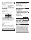
B
O
B
O
OR
USE "B" OR "O"
BUT NOT BOTH
ALL COMMON WIRES ARE OPTIONAL
AND MAY BE TAPED OFF
W
RH
B
O
RC
Y
G
C
OPTIONAL OPTIONAL
OPTIONAL OPTIONAL
OPTIONAL OPTIONAL
TC BC
FG
RCRH V 5R
HW 4
J
U
M
P
E
R
P
R
O
V
I
D
E
D
ALL COMMON WIRES ARE OPTIONAL
AND MAY BE TAPED OFF
**IF A "B" WIRE IN YOUR SYSTEM IS A
SYSTEM COMMON, THEN CONNECTING IT
AT THE "B" TERMINAL MAY CAUSE
DAMAGE TO YOUR SYSTEM
*IF Y AND "C" ARE BOTH PRESENT,
"C" IS THE COMMON WIRE
W
RH
B
O
RC
Y
G
C
DO NOT CONNECT
A "B" WIRE HERE
UNLESS YOU ARE SURE
THAT IT IS CORRECT
B TCC
FG
C* 6Y
RCRH V 5R
B**
HW 4
O
J
U
M
P
E
R
P
R
O
V
I
D
E
D
J
U
M
P
E
R
R
E
M
O
V
E
D
ALL COMMON WIRES ARE OPTIONAL
AND MAY BE TAPED OFF
**IF A "B" WIRE IN YOUR SYSTEM IS A
SYSTEM COMMON, THEN CONNECTING IT
AT THE "B" TERMINAL MAY CAUSE
DAMAGE TO YOUR SYSTEM
*IF Y AND "C" ARE BOTH PRESENT,
"C" IS THE COMMON WIRE
*IF Y AND "C" ARE BOTH PRESENT,
"C" IS THE COMMON WIRE
B**
W
RH
B
O
RC
Y
G
C
B TCC
FG
RRC
C* 6Y
RH V 5
HW 4
O
ALL COMMON WIRES ARE OPTIONAL
AND MAY BE TAPED OFF
W
RH
B
O
RC
Y
G
C
B TCC
FG
C*Y 6
RCR V
J
U
M
P
E
R
P
R
O
V
I
D
E
D
HEATING SYSTEMS COOLING SYSTEMS
4- or 5-WIRE WITH ONE TRANSFORMER 5- or 6-WIRE WITH TWO TRANSFORMERS
HEATING / COOLING SYSTEMS HEATING / COOLING SYSTEMS
DO NOT CONNECT
A "B" WIRE HERE
UNLESS YOU ARE SURE
THAT IT IS CORRECT