(PH521) ENGLISH
WIRE IDENTIFICATION AND WIRING SCHEMATICS
(PH521) ESPAÑOL
IDENTIFICACION DE CABLES Y DIAGRAMAS DE CABLEADO
(PH521) FRENCH
SCHÉMAS D'IDENTIFICATION DES FILS ET DU CÂBLAGE
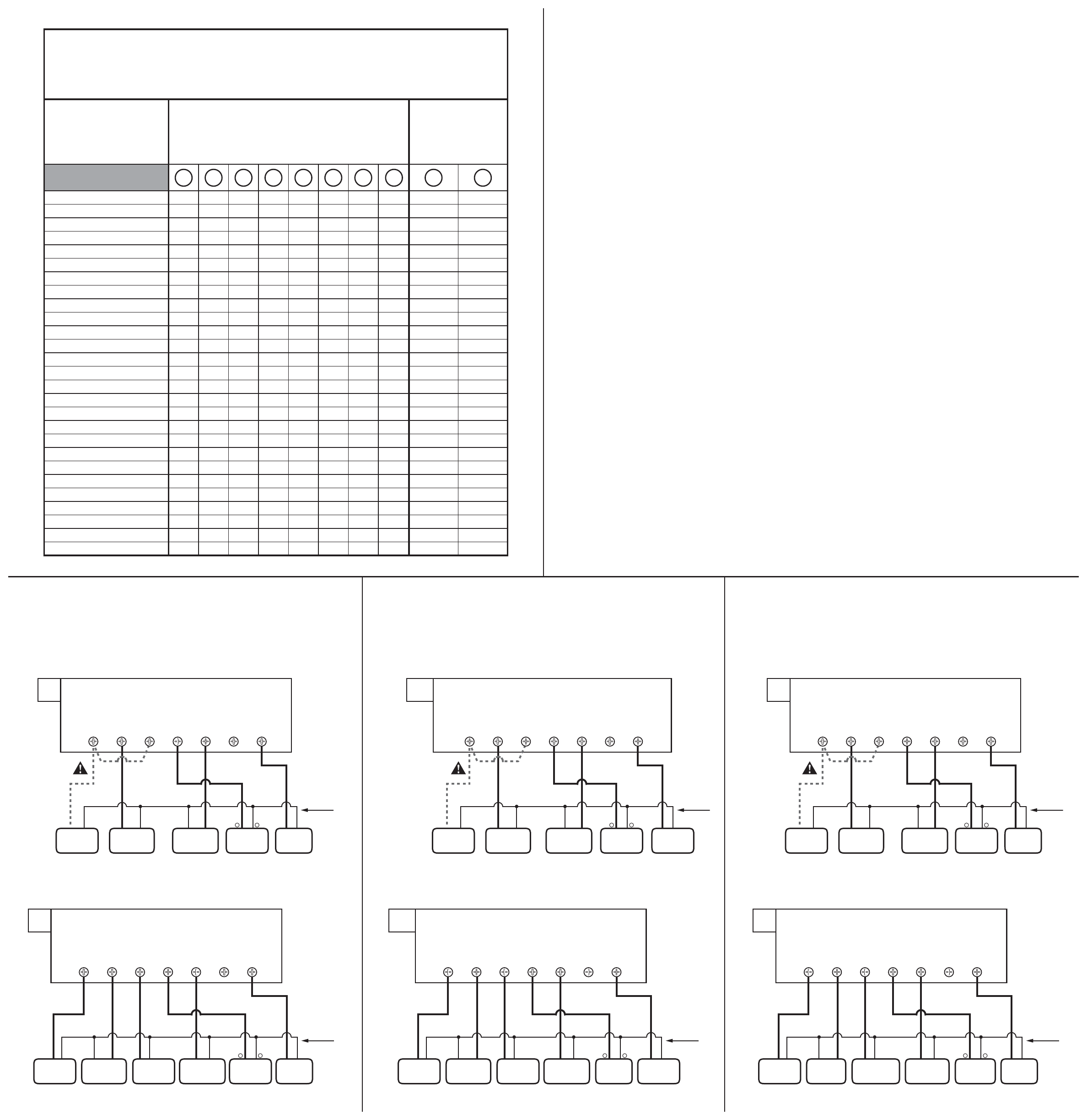
WIRING DIAGRAM NOTES:
(Important, please read all notes before connecting wires)
1. If the information provided does not clearly represent your system configuration, please refer to the “TECHNICAL
ASSISTANCE” section of this manual, and contact our support department before removing any of your existing
thermostat wiring.
2. The DASHED lines in wiring diagram #1 are optional depending upon your system type. Single stage heat pumps
will not have wires present for the “E” or “W2” terminals. For a 2-Heat / 1-Cool system with NO Emergency heat
wire, AUX heat will be connected to “W2”. A jumper wire may be placed in between the “E” and “W2” terminals
to allow Emergency Heat Mode.
3. For Heat Pumps, use either the “B” or “O” wire, NOT BOTH.
4. If “Y” and “C” wires are both present, then “C” is a common wire.
5. If you have a “B” wire in your system that is used as a common wire, connecting it to the “B/O” terminal on this
thermostat may damage your system and/or the thermostat.
NOTES DU DIAGRAMME DE CÂBLAGE :
(Il est important de lire toutes les notes avant de brancher les fils)
1. Si l'information fournie dans les diagrammes de câblage suivants ne représente pas clairement ou ne correspond
pas à votre système, veuillez consulter la section de « L'AIDE TECHNIQUE » de ce manuel et nous contacter
avant de retirer tout câblage actuel du thermostat.
2. Les lignes en TRAITS TIRÉS du diagramme de câblage 1 sont optionnelles et leur utilisation dépend de votre
type de système. Les pompes à chaleur à un étage n'ont pas de fils pour les bornes « E » ou « W2. » Pour un
système à 2 chauffage / 1 refroidissement SANS fil de chauffage d'urgence, la chaleur AUX sera branchée à « W2
». Un fil de calier peut être placé entre les bornes « E » et
« W2 » pour permettre l'utilisation du mode de chau ffage d'urgence.
3. Pour les pompes à chaleur, utilisez soit le fil « B » ou « O », NON PAS LES DEUX.
4. Si vous avez les fils « Y » et « C », alors le « C » est le fil commun du système.
5. Si vous avez un fil « B » dans votre système et si ce fil est utilisé comme fil commun, le brancher à la borne «
B/O » du thermostat pourrait endommager votre système et/ou le thermostat.
NOTAS DEL DIAGRAMA DEL CABLEADO:
(Importante, por favor lea todas las notas antes de conectar los cables)
1. Si la información que se proporciona en los siguientes diagramas de cableado no representa o no coincide
claramente con la configuración de su sistema, por favor consulte la sección "ASISTENCIA TÉCNICA" de este
manual y comuníquese con nosotros antes de retirar cualquier cable de su termostato.
2. Las líneas PUNTEADAS en el diagrama del cableado #1 son opcionales, dependiendo del tipo de sistema. Las
bombas de calefacción de una fase no contienen cables para las terminales “E” ni “W2”. Para un sistema de 2
fases de calefacción y una de enfriamiento, NO se conecta el cable de calefacción de emergencia ni el auxiliar
(AUX) en la terminal “W2”. Puede colocar un cable para formar un puente entre las terminales “E” y “W2” y
permitir un modo de calefacción de emergencia.
3. Para las bombas de calefacción, utilice el cable “B” o el cable “O”, NUNCA USE AMBOS.
4. Si tanto el cable “Y” como el “C” están presentes, entonces es más probable que el “C” sea el cable común del
sistema.
5. Si en su sistema hay un cable “B” que se utiliza como cable común, no lo conecte a la terminal “B” ni “O” del
termostato, pues podría dañar tanto su aparato como su sistema.
HEAT PUMP TERMINAL CROSS REFERENCE CHART
TABLEAU DE RÉFÉRENCE CROISÉE DE BORNE DE POMPE À CHALEUR
TABLA DE REFERENCIA PARA LA TERMINAL DE LA BOMBA DE CALEFACCIÓN
ARCO / Friedrich
ARCO / Snyder General
BARD
BARD, HP, WH, MHP, HPQ
BDP / BRYANT
CARRIER
CARRIER 5Q
CARRIER 50Q, QT382
COLEMAN
GE BAY
HEIL-QUAKER / Whirlpool
JANITROL / Goodman
LENOX TYPICAL HP6
LENOX HP8
LENOX HP9, 10
LENOX HP16, 18, 19
MAGIC CHEF PE
RHEEM / RUUD
SNYDER GENERAL H-R811
TRANE
WEATHERKING
WESCO
WESCO / ADDISON
WESTINGHOUSE H50
WESTINGHOUSE HE
WHITE RODGERS
YORK
HEAT PUMP BRAND
MARQUE DE POMPES
À CHALEUR
MARCA DE LA BOMBA
DE CALEFACCIÓN
CORRESPONDING TERMINALS
BORNES
CORRESPONDANTES
TERMINALES
CORRESPONDIENTES
TAPE OFF (NOT USED)
RUBAN RETIRÉ
(NON UTILISÉ)
DESPRENDIMIENTO
(NO UTILIZADO)
W2
W1
W2
W2
W1
Y1
W2
W2
W2
W
W
W2
Y
Y
Y
Y
W
W2
W1
W
E
W2
W
H2
W2
W
W2
O
O
O
O
O
V
O
O
O
R
R
R
R
O
O
O
Y1
Y1
O
O
O
O
O
RC
R
R
R
R
R
R
R
RED
R
R
R
V/VR
V/VR
V/VR
V/VR
R
R
R
R
R
R
R
R
V/VR
R
R
R
Y
Y
Y1
Y
Y
Y
Y, W1
Y
Y
Y
Y
Y
M
M
M
M
Y
Y
Y
Y
W1
W1
W1
Y
C
Y
Y
Y
G
G
G
G
G
G
G
G
G
G
G
G
F
F
F
F
G
G
G
G
G
G
G
G
F
G
G
G
X2
E
E
E
E
E
to W2
E
X2
E
E
E
E
E
E
X2
E
E
E
E
E
B
B
W1
B
Z
B
C
C
X
X
C
C
C
C
BLACK
B
B
C
X
X
X
X
C
X
C
B
C
C
X
X
X
C/X1
B
C
T
T
L
X
L
L
F
L
L
L
L
L
L
F
L1
L
X
L
TYPICAL 24 VOLT, SINGLE-STAGE HEAT PUMPS AND
2-STAGE HEAT / 1-STAGE COOL HEAT PUMP SYSTEMS
WITH NO EMERGENCY HEAT WIRE
# 1
Y R CB/O G
+
-
HEAT
PUMP
AUX.
HEAT
SYSTEM
XFMR
REVERSING
VALVE
System
Common
BLOWER
FAN
**Refer To
Wiring Note #2
W2 E
TYPICAL 24 VOLT, 2-STAGE HEAT / 1-STAGE COOL
HEAT PUMP SYSTEMS
WITH EMERGENCY HEAT WIRE PRESENT
# 2
Y EW2 R CB/O G
+
-
HEAT
PUMP
EMERGENCY
HEAT
AUX.
HEAT
SYSTEM
XFMR
REVERSING
VALVE
System
Common
BLOWER
FAN
LES POMPES À CHALEUR À UN ÉTAGE TYPIQUES DE 24 VOLTS
ET LES SYSTÈMES DE POMPE À CHALEUR À 2 ÉTAGES DE CHALEUR /
1 ÉTAGE DE REFROIDISSEMENT SANS FIL DE CHAUFFAGE D'URGENCE
N° 1
Y R CB/O G
+
-
POMPE À
CHALEUR
AUX.
CHALEUR
SYSTÈME
XFMR
ROBINET
INVERSEUR
Système
commun
VENTILATEUR
SOUFFLANT
** Reportez-vous à la note
de câblage numéro 2
W2 E
LES SYSTÈMES DE POMPES À CHALEUR À
UN ÉTAGE DE REFROIDISSEMENT / 2 ÉTAGES DE CHAUFFAGE
TYPIQUES DE 24 VOLTS AVEC UN FIL DE CHAUFFAGE D'URGENCE
N° 2
Y EW2 R CB/O G
+
-
POMPE À
CHALEUR
CHAUFFAGE
D'URGENCE
AUX.
CHALEUR
SYSTÈME
XFMR
ROBINET
INVERSEUR
Système
commun
VENTILATEUR
SOUFFLANT
BOMBAS TÍPICAS DE CALEFACCIÓN DE UNA FASE Y SISTEMAS
TÍPICOS CON BOMBA DE CALEFACCIÓN DE 2 FASES
Y AIRE ACONDICIONADO DE 1 FASE, TODOS DE 24 VOLTIOS
# 1
Y R CB/O G
+
-
BOMBA DE
CALEFACCIÓN
CALEFACCIÓN
AUX.
SISTEMA
XFMR
VÁLVULA DE
INVERSIÓN
Sistema
Común
VENTILADOR
**Consulte la Nota
de cableado #2
W2 E
SISTEMAS TÍPICOS CON BOMBA DE CALEFACCIÓN DE 2 FASES
Y AIRE ACONDICIONADO DE 1 FASE DE 24 VOLTIOS,
CON CABLE DE CALEFACCIÓN DE EMERGENCIA
# 2
Y EW2 R CB/O G
+
-
BOMBA DE
CALEFACCIÓN
CALEFACCIÓN DE
EMERGENCIA
CALEFACCIÓN
AUX.
SISTEMA
XFMR
VÁLVULA
DE INVERSIÓN
Sistema
Común
VENTILADOR
52125


