3
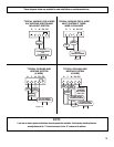
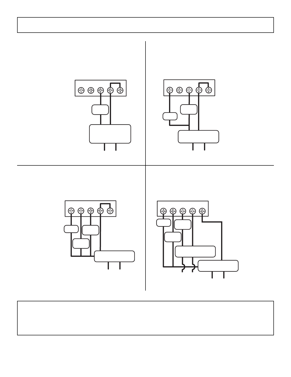
TYPICAL COOLING AND
HEATING SYSTEM
(4-WIRE)
GYWRHRC
Figure 10
110
GAS
VALVE
COOL
COMP
FAN
24 VAC HEAT
TRANSFORMER
110
TYPICAL COOLING AND
HEATING SYSTEM
(5-WIRE)
GYWRHRC
FAN
COOL
COMP
GAS
VALVE
24 VAC HEAT
TRANSFORMER
110
Figure 11
24 VAC COOL
TRANSFORMER
REMOVE
JUMPER
BETWEEN
RH & RC
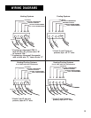
TYPICAL HOOKUP FOR 3-WIRE
HEAT SYSTEM IF THIRD
WIRE IS FAN WIRE
TYPICAL HOOKUP FOR 2-WIRE
24V HEATING SYSTEM AND
MILLIVOLT SYSTEM
GYWRHRC
Figure 8
GAS
VALVE
110
24 VAC
TRANSFORMER
OR
THERMOPILE
GYWRHRC
Figure 9
GAS
VALVE
110
FAN
24 VAC
TRANSFORMER
These diagrams below are provided for new installations or unreferenced wires.
NOTE
if you have an electric system and the blower does not operate after installation, find the factory installed yellow wire
currently attached to the “Y” terminal and move it to the “A” terminal on the sub-base.


