


3
On replacement installations, mount the new thermostat in place of the old one unless the conditions listed
below suggest otherwise. On new installations, please follow these general guidelines:
1
.Mount the thermostat on an inside wall, about 5 ft. (1.5m) above the floor.
2.Do not locate the thermostat where air circulation is poor such as in a corner, alcove, or behind a door that
is normally left open. Do not locate the thermostat where unusual heating or cooling conditions may be
present, such as: direct sunlight, above a lamp, television, or radiator, or on a wall next to an exterior door
or window.
3.Do not locate in a damp environment, as this can lead to corrosion that may shorten thermostat life. If
painting or construction work is still ongoing, cover the thermostat completely or wait until this work is
complete before installation.
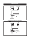
• This thermostat is powered by the 24 VAC from the system, and must have a System Common wire (negative
[-] side of the 24V transformer) attached to the “C” terminal adjacent to the “RH” wire connection.
• If you only have three wires going to the thermostat location (RH, C, and W), then your hydronic zone valve
will need to receive its Common connection from the transformer. If your hydronic zone valve cannot
receive a Common Power connection directly from the transformer, the thermostat can provide Common
Power to the zone valve using the optional “C” terminal output
along with the “W” terminal for heating
activation, but a fourth wire must be added.
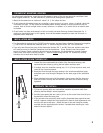
1. Loosen the screw underneath the middle of the thermostat housing, and
separate the two halves by pulling the two bottom surfaces apart.
2. If needed, strip wire insulation leaving only 1/4 in. (6 mm) bare wire ends, and
clean off any corrosion present.
3. Route the wires through the large opening in the new thermostat base plate,
and attach your wires using the diagrams on the back page of this installation
sheet.
4. When attaching the wires to the thermostat, please ensure that the bare wire
ends are held all the way into the terminal block while the screws are being
tightened.
1. Fill the wall opening with non-combustible insulation to prevent drafts from
affecting the thermostat’s normal operation.
2. Hold the base against the wall, and try to line up the screw holes from the prior
thermostat to mount the base plate
3. If the previous holes cannot be used, hold the thermostat base against the wall
so that it appears straight and level (position the base for best appearance) and
mark for the new screw holes. Attach the base to the wall using the screws
provided (use the supplied plastic anchors if needed when mounting to a soft
material such as drywall).
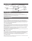
THERMOSTAT MOUNTING LOCATION:
COMPLETE THE INSTALL:
INSTALLATION OF NEW THERMOSTAT:
INSTALLATION NOTES: