


NOTE: DIAGRAMS & ILLUSTRATIONS NOT TO SCALE.
5
MINIMUM CLEARANCES TO COMBUS-
TIBLES
Mantel Clearance: Combustible and Non-com-
bustible mantels may be installed at any height
above the top of the face of fireplace.
Cat. No. H3427
Model: MPE-33R
Description: Merit Plus Electric Fireplace,
33” Radiant
Shipping Weight: 81 lb.'s (36.75 KG)
Packaging:
41” x 17 3/4” x 33 1/2”
(1040 mm x 451 mm x 850 mm)
14.1 cu. ft.
Power Requirements:
(120 Volt, 60 Hz.)
Rated Wattage - 1600 Watts
Amperage - 13.33 Amps
(240 Volt, 60 Hz.)
Rated Wattage - 3000 Watts
Amperage - 12.5 Amps
Blower CFM: 83 CFM
(120 V): 5,461 BTU/HR
(240 V): 10,239 BTU/HR
FIREPLACE SPECIFICATIONS
This appliance is an electric fireplace designed
to be framed in with combustible materials (up
to the edge of the appliance). A drywall lip at
the top of the fireplace and 4 nailing flanges
on the sides of the appliance is provided to
facilitate installation.
Hearth Protection: A hearth is not mandatory,
but it is recommended for aesthetic purposes.
Secure the hearth extension to the floor to
prevent possible shifting. Do no block the air-
flow beneath the appliance (read the following
WARNING).
Clearances
Sides 0 inches - 0 mm
Floor 0 inches - 0 mm
Top 0 inches - 0 mm
Table 2
WARNING
Electrical wiring must comply
with local building codes and
other applicable regulations to
reduce the risk of fire, electrical
shock and injury to individuals.
IMPORTANT
Any electrical re-wiring of this
appliance must be done by a
qualified electrician.
WARNING
Do not use this fireplace if any
part of it has been underwater.
Immediately call a qualified
service technician to inspect the
fireplace and replace any part of
the electrical system which has
been under water.
3. Wire a dedicated, properly fused circuit with
an Amp rating for the appropriate voltage
(120 V - 15 Amps or 240 V - 20 Amps).
A dedicated circuit is required to prevent
overloading a house circuit in cases of having
multiple appliances on the same circuit.
Use an outlet that is protected by a ground
fault circuit interrupter where required by
electrical code.
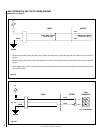
4.
(If applicable) Make wall mount wall switch
or wall thermostat connections as outlined
on Pages 11 & 12.
5. Perform a function test. See Manual Control
Panel Operation
on Page 6 and Remote
Control Operation
on Page 7.
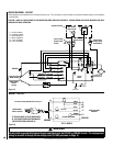
ELECTRICAL CONNECTIONS
Refer to the electrical diagrams on Pages 10
to 14.
PRE-INSTALLATION
Before You Start
Check appliance for any concealed damage.
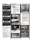
DETAILED INSTALLATION STEPS
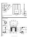
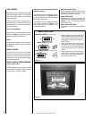
1. Complete the framing opening to the dimen-
sions specified in Figure 2.
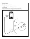
2. Prepare the connections to power source:
120 Volt Connections - Locate the power
cord on the left side of the unit and connect
it to the outlet installed during the framing
(see Figure 2). Verify that the power to the
receptacle is off.
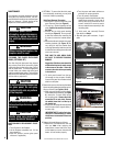
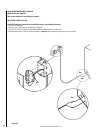
Hard wired installation:
Ensure that there is a minimum of 8" of the
service cable for connection to the junction
box on the fireplace.
- Loosen four screws to remove the junction
box cover plate.
- Disconnect and remove the 120 Volt power
cord from the fireplace wires.
- Position the fireplace into the framed-in
opening. Attach fireplace to frame using
nailing flanges provided.
- Complete the wiring to the fireplace as
shown on Page 10.
- Place all wire connectors inside the junction
box.
- Attach junction box cover plate with four
screws.
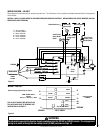
240 Volt Connections - Ensure that there
is a minimum of 8" of the service cable
for connection to the junction box on the
fireplace.
- Loosen four screws to remove the junction
box cover plate.
- Disconnect and remove the 120 Volt power
cord from the fireplace wires.
- Position the fireplace into the framed-in
opening. Attach fireplace to frame using
nailing flanges provided.
- Complete the wiring to the fireplace as
shown on Page 11.
- Place all wire connectors inside the junction
box.
- Attach junction box cover plate with four
screws.
The fireplace wires L1, L2, N, N1, N2 and
G are attached to the rear of the junction
box cable clamp for easy access.