8
NOTE: DIAGRAMS & ILLUSTRATIONS ARE NOT TO SCALE.
To install the front glass enclosure panel,
proceed as follows:
1. Retrieve the glass door frame. Visually
inspect the gasket on the backside of the
panel. The gasket surface must be clean,
free of irregularities and seated fi rmly.
2. Position the door frame in front of the fi rebox
opening and engage the top fl ange over the
lip at the top of the fi rebox opening.
3. Swing the door down and back. Ensure the
gasket seats evenly as the door draws shut.
Engage the Vee-fl ange at the bottom of the
door with the latch and close the latch to
secure the door.
4. Reinstall the top louver assembly or radiant
panel.
These appliances are designed to operate only
with the front glass enclosure panel properly
installed. Generally, the glass enclosure panel
should not be removed except to gain access
to the components within the fi rebox, and the
appliance may only be operated without the
front glass enclosure panel in place for very
brief periods of time during initial appliance
checkout and adjustment.
During this appliance checkout and adjust-
ment period, a potential safety hazard exists
- EXERCISE EXTREME CAUTION to prevent
the occurrence of any burn injuries from the
exposed fl ames or hot surfaces. Also note,
that while the front glass enclosure panel is
removed, the fl ame appearance will appear to
be smaller than normal.
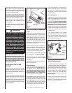
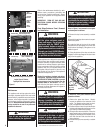
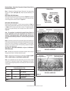
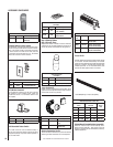
Refer to Figure 6 and remove the front glass
enclosure panel as follows:
1. Remove the top louver assembly or radiant
panel.
2. Open the hinged drop-down control compart-
ment access panel.
3. Locate the latch at the top of the control
compartment and disengage it from the door
frame bottom Vee-fl ange, pulling down on its
handle to open it.
4. Swing the bottom of the door out and raise
it slightly to lift the top fl ange of the door frame
away from the appliance.
Figure 6
Maintenance
The appliance and venting system should be
thoroughly inspected before initial use and at
least annually by a qualifi ed service technician.
However, more frequent periodic inspections
and cleanings should be performed by the ho-
meowner. Homeowner must contact a qualifi ed
service technician at once if any abnormal
condition is observed.
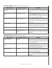
Refer to the maintenance schedule for main-
tenance tasks, procedures, periodicity and
by whom they should be performed. Always
verify proper operation of the appliance after
servicing.
IMPORTANT: TURN OFF GAS AND ANY
ELECTRICAL POWER BEFORE SERVICING
THE APPLIANCE.
Front Glass Enclosure Panel, Removal
and Installation.
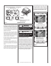
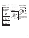
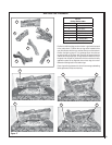
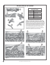
Figure 5
Blocked Flue Safety Limit Location
Inside View of Firebox -
Top/Right Side Intersection
Detail A
Detail C
Detail B
Scoop
Scoop Securing Screws
Fire Box Top
Lintel Securing Screw
Hole in Cabinet Top
Fire Box Top
Limit
Limit/Bracket
Securing Screws
Lintel Securing-Scre
w
Hole in Cabinet Top
Wire
Termianls
Back Of
Limit
Switch
Cabinet
Corner
Door
Frame
Latch
Glass Door
Firebox Floor
Bottom Vee-flange
Door Frame
Top Flange
Door Frame
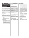
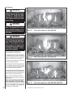
IMPORTANT
The glass door of this appliance must
only be replaced as a complete unit as
provided by the manufacturer. Do not
attempt to replace broken, cracked
or chipped glass separately.
WARNING
Never operate the appliance with-
out the glass enclosure panel in
place and secure. Do not operate
appliance with the FRONT glass
panel cracked, broken or missing.
Replacement panels are available
through your local LENNOX Dealer
and must be installed by a licensed
or qualifi ed service technician.
WARNING
Handle the glass with extreme care!
Tempered glass is susceptible to
damage (scratches, for example)
– Handle glass door (glass enclosure
panel) gently while reinstalling it.
WARNING
Do not attempt to substitute the mate-
rials used on this door, or replace
cracked or broken glass with any
materials other than those provided
by the appliance manufacturer.
WARNING
Turn off gas and electrical power
before servicing the appliance.


