


© LABOR STRAUSS SICHERUNGSANLAGENBAU GMBH • A-1231 WIEN • WIEGELESTRASSE 36 • TEL +43 1 52114-0 • FAX +43 1 52114-27
OFFICE@LST.AT • WWW.LST.AT • ALL RIGHTS RESERVED
BC216-1_DBL_LST_EN_0804.PDF • PAGE 2
ABuilding Safety. Building Security.
Clear Concept
The fi re detection control panel BC216-1 constitutes
the basic component of Series BC216 and has been
designed for use in small and mid-sized systems. De-
pending on its confi guration, it provides the following
features:
• The Conventional Detector Interface GIF8-1 permits
the connection of automatic detectors and manual
call points in conventional technology as well as spe-
cial detectors with contact output. Individual detector
identifi cation can be achieved by means of an optio-
nal address module.
• Detectors and modules in ADM loop technology can
be connected to the Loop Interface LIF64-1. Depen-
ding on the parameterisation, either the Apollo/Disco-
very protocol or the System Sensor/200 protocol is
used to achieve bi-directional data transfer.
• The BC216-1 is able to control up to 252 detectors
or modules, 144 detector zones, 128 actuations, 10
transmission devices and 99 alarming devices.
• Since the BC216-1 is compatible to LST fi re detec-
tion control panels of previous generations, the ex-
change or expansion of existing systems in conventi-
onal technology or ADM loop technology is possible.
The existing detector installation can be used without
changes.
• The optional Fire Brigade Interface FWI2-1 serves
for the connection of two independent transmitting
devices for a direct interconnection to a designated
alarm respondent (e.g., the fi re brigade) as well as
for the connection of a country-specifi c fi re brigade
control unit. By using the Fire Brigade Interface Addi-
tional Board FWZ2-1, a line supervision for both of the
transmitting devices is accomplished.
• Customizable outputs and logical combinations of
detectors and detector zones for the activation of
external controls and alarming devices facilitate ma-
ximum fl exibility. Thus, no additional expenses arise
for external relays, logic gates or timers. Thanks to
the wide range of parameterisation possibilities, indi-
vidual requirements even under the most diffi cult am-
bient conditions can be combined into a reasonable
fi re protection strategy.
• By integrating input and output modules on any positi-
on in the loop you can realize enablements or disable-
ments as well as control tasks in your system without
having to care for additional wires.
• The free combination of detectors and modules into
logic sectors allows for the joint operation of defi ned
parts of the system even beyond loop limits. Up to
199 sectors can be controlled by the BC216-1.
• The use of unshielded loop cables allows for cost-
saving and uncomplicated installation as well as for
the possibility of reusing the existing cabling.
• The LC text display shows events with the full infor-
mation such as fl oor, room identifi cation as well as
date and time. This allows for quick and targeted
reaction in the event of a fi re as well as for easy main-
tenance.
• An event memory allows for the display of the latest
500 events at any time, including all required informa-
tion. Thus, all system conditions and user operations
that occurred are documented in a clearly laid out
way.
• At a central processing board failure, the diversifi ed
redundancy concept ensures secure alarm recogniti-
on.
• The processor-monitored power supply ensures per-
manent surveillance and charging of the batteries.
This way, even during a mains power failure the un-
troubled and uninterrupted operation (for more than
72 hours depending on the design) is guaranteed.
• Three hierarchized authorization levels for operation
and parameterisation facilitate a high degree of secu-
rity against unauthorized access.
• The control panel is easily operated menu-driven via
the display and operating fi eld. Clear instructions on
the display guide the user during commissioning,
operation and maintenance.
• The parameter data can be entered either on the con-
trol panel via the display and operating fi eld or via a
PC keyboard or, in a more comfortable way, created
on a PC by means of the parameter setup software
PARSOFT and loaded into the control panel. Thus, a
quick and effi cient transfer of the system confi gurati-
on into the control panel is guaranteed.
• AUTO setup facilitates parameterisation when the
control panel is commissioned or expanded and thus
helps to save time.
• After commissioning, the panel‘s basic functions im-
mediately make it ready for operation. A monitored
siren output and dry relay contacts for alarm and fault
are available by default.
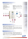
The fl at wall mount cabinet allows for an easy mounting
in virtually any place of the building. Thanks to its mo-
dern, ageless design, architectural requirements and
demands of the respective regulations are ideally com-
bined. The compact design allows for the accommoda-
tion of the function modules, the auxiliary modules and
batteries up to 22Ah apart from the central processing
board in the standard case. If a higher battery capacity
is needed, an auxiliary case of the same design is avai-
lable. The BC216-1 thus stands for modularity and easy
expansion.
This product complies with all relevant standards of
EN 54 and is VdS-certifi ed. In addition, the product also
holds several country-specifi c approvals and certifi ca-
tes. LST‘s high quality level is secured by a permanent-
ly monitored quality management system certifi ed to
ISO 9001.