28 Maintenance
© Travis Industries 4071130 100-01196_000
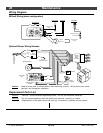
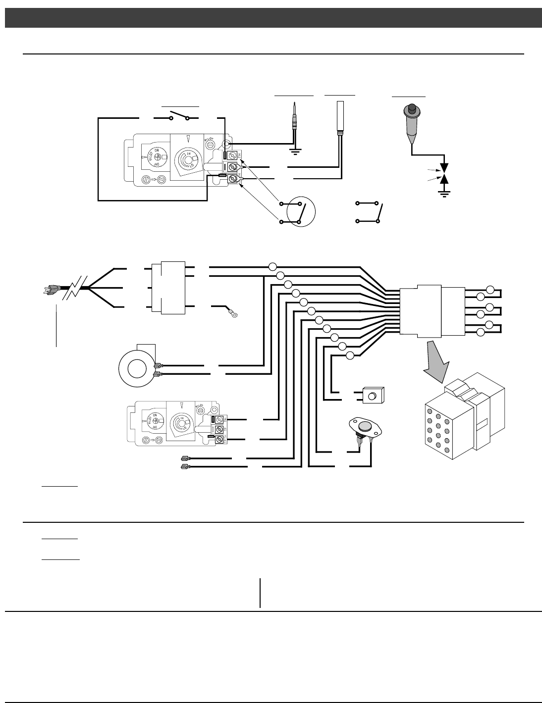
Wiring Diagram
Millivolt Wiring (stock configuration)
Orange
White
Piezo Igniter
Thermopile
Red
Thermocouple
Copper Co-Axial
Wire
Red
Optional Remote
Control
Spark Electrode
Pilot Hood
On/Off Switch
Brown
Optional
Thermostat
Optional Blower Wiring Harness
7
4
10
9
1
3
Optional Blower(s)
Green
Hot
(black)
Common
(white)
Ground
(green)
Blower
Snap Disk
Power In
Molex
Connector
Power Supply
Ground
(attached to stove)
White
Black
1
3
5
7
2
4
6
8
9
12
11
10
3
6
White
9
2
5
Black
Remote
Control
Molex
Connector
8
11
Blue
Blue
Optional Regulator
Solenoid
1
4
Black
Black
7
Black
Black
10
Red
Brown
Rheostat
Gas Control
Valve
Caution: Label all wires prior to disconnection when servicing controls. Wiring errors can cause
improper and dangerous operation.
Replacement Parts List
Caution: Use only Travis Industries replacement parts. Do not use substitute materials.
Warning: Do not operate appliance with the glass front removed, cracked, or broken.
Replacement of the glass should be done by a licensed or qualified service person.


