


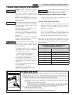

Hazard definitions
The following defined terms are used throughout this manual to bring attention to the presence of hazards of various risk levels or
to important information concerning the life of the product.
2
ƽ DANGER
ƽ WARNING
ƽ CAUTION
CAUTION
NOTICE
DANGER indicates an imminently hazardous situation which, if not avoided, will result in death or serious
injury.
WARNING indicates a potentially hazardous situation which, if not avoided, could result in death or serious
injury.
CAUTION indicates a potentially hazardous situation which, if not avoided, may result in minor or moderate
injury.
CAUTION used without the safety alert symbol indicates a potentially hazardous situation which, if not
avoided, may result in property damage.
NOTICE indicates special instructions on installation, operation, or maintenance that are important but not
related to personal injury or property damage.
HAZARD DEFINITIONS . . . . . . . . . . . . . . . . . . . . . . . . . . 2
PLEASE READ BEFORE PROCEEDING . . . . . . . . . . . . 3
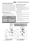
1. GENERAL INFORMATION
Operating Restrictions . . . . . . . . . . . . . . . . . . . . . . . . . . . . 4
Single-Wall Heat Exchanger . . . . . . . . . . . . . . . . . . . . . . . 4
2. PRE-INSTALLATION
Locating the Tank . . . . . . . . . . . . . . . . . . . . . . . . . . . . . . . 5
Recommended Clearances . . . . . . . . . . . . . . . . . . . . . . . . 5
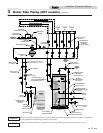
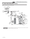
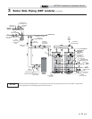
3. BOILER SIDE PIPING (SDT MODELS)
Zone with Circulator to Aquastat . . . . . . . . . . . . . . . . . . . . 6
Zone with Valve to Aquastat . . . . . . . . . . . . . . . . . . . . . . . 6
DHW Prioritization . . . . . . . . . . . . . . . . . . . . . . . . . . . . . . . 6
Multiple Tank Connections (Boiler Side) . . . . . . . . . . . . . . 6
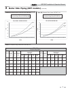
Table 3A - 3B - Pressure Drop Charts . . . . . . . . . . . . . 7
Table 3C - Pressure Drop Values . . . . . . . . . . . . . . . . . 7
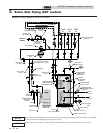
Piping Diagrams . . . . . . . . . . . . . . . . . . . . . . . . . . . . . . . . 8-11
4. DOMESTIC SIDE (TANK) PIPING
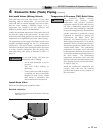
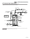
Basic Domestic Piping . . . . . . . . . . . . . . . . . . . . . . . . . 11
Multiple Tank Domestic Water Piping . . . . . . . . . . . . . 11
Domestic Water Piping for Distant Fixtures . . . . . . . . .11
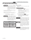
Anti-scald Valves (Mixing Valves) . . . . . . . . . . . . . . . . 12
Install Drain Valve . . . . . . . . . . . . . . . . . . . . . . . . . . . 12
Temperature and Pressure (T&P) Relief Valve . . . . . 12
Table 4A - Minimum Relief Valve (AGA Rating) . . 13
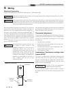
5. WIRING
Electrical Connection and Thermostat Setup . . . . . . . . . .16
Indirect Water Heater Sensor Setup (Knight Boiler) . . . . 18
Install Tank Sensor . . . . . . . . . . . . . . . . . . . . . . . . . . . . . 18
Indirect Water Heater Controlled Using Aquastat and Zone
Circulator . . . . . . . . . . . . . . . . . . . . . . . . . . . . . . . . . . . . . 19
6. START-UP AND CHECK-OUT . . . . . . . . . . . . . . . . . 20
7. MAINTENANCE
Maintenance Schedule . . . . . . . . . . . . . . . . . . . . . . . . . . 21
To Fill the Water Heater . . . . . . . . . . . . . . . . . . . . . . . 21
To Drain the Water Heater . . . . . . . . . . . . . . . . . . . . . 21
8. PERFORMANCE DATA
Performance Data Charts . . . . . . . . . . . . . . . . . . . . . . . . 22-24
9. High Output Piping
High Domestic Hot Water Usage . . . . . . . . . . . . . . . . 25
Series Piping . . . . . . . . . . . . . . . . . . . . . . . . . . . . . . . 25-26
Parallel Piping. . . . . . . . . . . . . . . . . . . . . . . . . . . . . .25-27
REVISION NOTES . . . . . . . . . . . . . . . . . . . . . Back Cover
Contents