


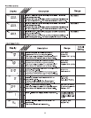
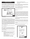
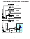


The control is no longer able to read the boiler return sen-
sor due to an open circuit (FIG. 59). The control will contin-
ue to operate normally. Locate and repair the problem as
described in INS7141. To clear the error message from the
control after the sensor has been repaired, press either the
Menu or Item button.
If the boiler return sensor was deliberately removed from
the control, remove power from the control and repower the
control to clear the error message.
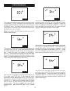
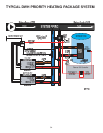
The control has detected no increase in the supply water
temperature within the BOIL Alarm time setting. Check to
see if the boilers are operating properly using the Test but-
ton. To reset the alarm, press and hold the up and down
arrow buttons for 5 seconds while in the VIEW menu.
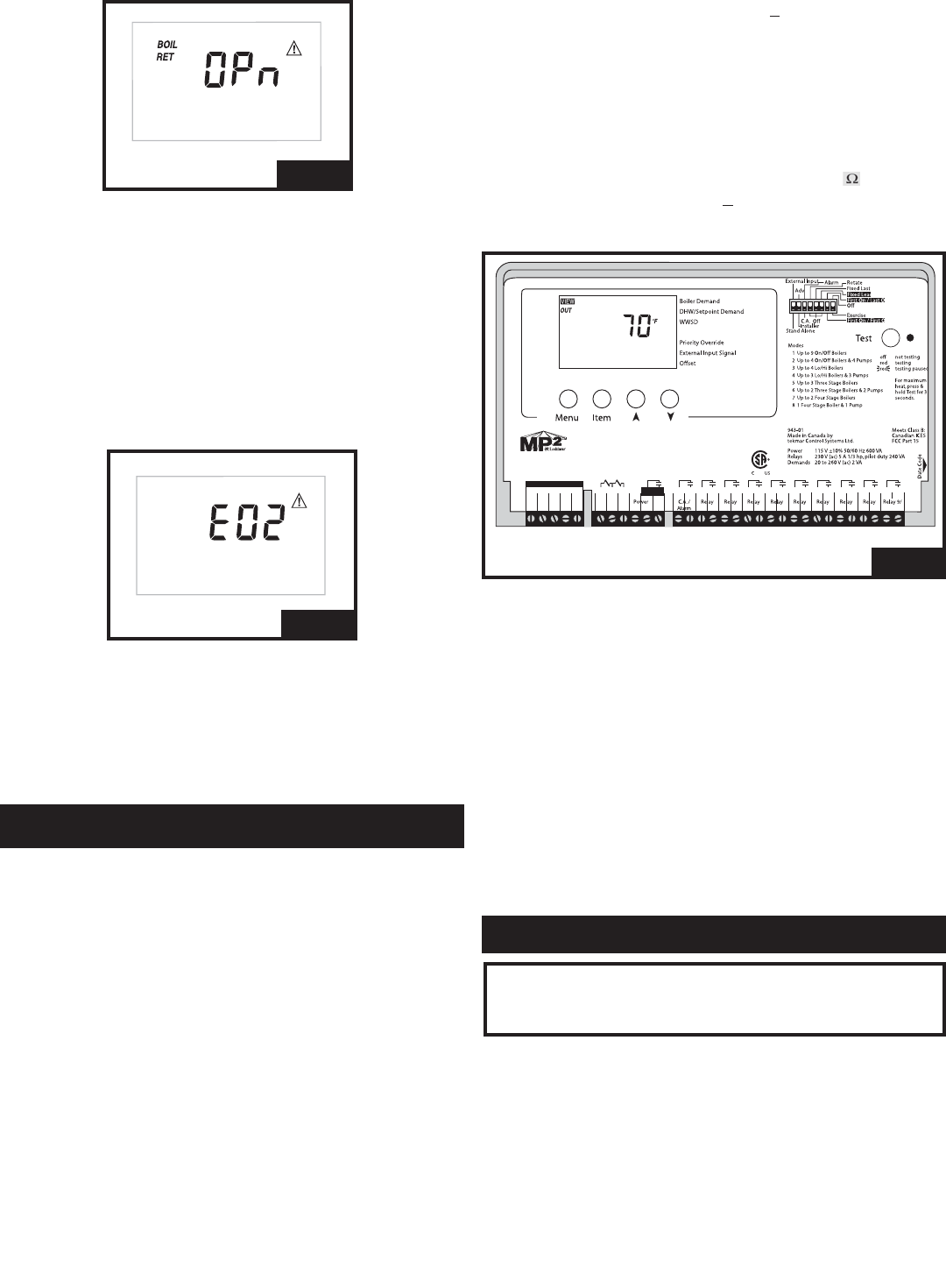
MP
2
NINE STAGE BOILER & DHW / SET POINT
Control - Microprocessor PID control; This
is not a safety (limit) control.
Packaged Weight - - 3.3 lb. (1500 g), Enclosure A, blue
modified PPO plastic
Dimensions - 6-5/8" H x 7-9/16" W x 2-13/16" D
(170 x 193 x 72 mm)
Approvals - CSA C US, meets ICES & FCC
regulations for EMI/RFI
Ambient Conditions - Indoor use only, 30 to 120°F (0 to
50°C), <95% RH non-condensing
Power Supply - 115 V (ac) +
10% 50/60 Hz
600 Va
Relay Capacity - 230 V (ac) 5 A 1/3 hp pilot duty
230 VA
Demands - 20 to 260 V (ac) 2 VA
Sensors Included - NTC thermistor, 10 k @ 77°F
(25°C +
0.2°C) B=3892
The installer must ensure that this control and its wiring are
isolated and/or shielded from strong sources of electromag-
netic noise. Conversely, this Class B digital apparatus com-
plies with Part 15 of the FCC Rules and meets all require-
ments of the Canadian Interference - Causing Equipment
Regulations. However, if this control does cause harmful
interference to radio or television reception, which is deter-
mined by turning the control off and on, the user is encour-
aged to try to correct the interference by re-orientating or
relocating the receiving antenna, relocating the receiver
with respect to this control, and/or connecting the control to
a different circuit from that to which the receiver is connect-
ed.
31
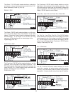
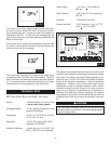
FIG. 59
FIG. 60
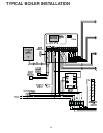
TECHNICAL DATA
21
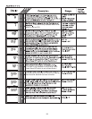
Com
SupRet Sw DemDem DH N– + L P1 1 1 2 2 3 3 4 4 5 5 6 6 7 7 8 8 DHW
3
BoilBoilOutUnO BoilComSetpPrim
4 5
6
7
8
9
10
11
12
1314
15
16
1718
19
2021
22
2324
25
26 2827
29
3031
Nine Stage Boiler & DHW / Setpoint
Do not apply power
Signal wiring must be rated at least
H2026B
FIG. 61
ƽƽ
CAUTION
The nonmetallic enclosure does not provide grounding
between conduit connections. Use grounding type bush-
ings and jumper wires.