


> Low Voltage Terminal Strip
> 24 VAC Auxiliary Device Relay
> Auxiliary Proving Switch Contacts
> Flow Switch Contacts
> Alarm on Any Failure Contacts
> Runtime Contacts
> DHW Thermostat Contacts
> Room Thermostat Contacts
> System Sensor Contacts
> DHW Tank Sensor Contacts
> Outdoor Air Sensor Contacts
> Cascade Contacts
> 0-10 VDC BMS External Control Contact
Optional Equipment
> Alarm Bell on Any Failure
> Condensate Neutralization Kit
> High & Low Gas Pressure Switches w/ Manual
Reset (KB500-KB800)
> Low Water Cutoff w/Manual Reset & Test
> SMART SYSTEM PC Software
> Stainless Steel Vent Kits (KB700-KB800)
> Multi-Stack Frame
Firing Codes
> M9 Standard Construction
> M7 California Code
> M13 CSD1 / FM / GE Gap (KB500-KB800)
Standard Features
> Up to 94.6% Thermal Efficiency
> Modulating Burner with 5:1 Turndown
> Direct-Spark Ignition
> Low NOx Operation
> Sealed Combustion
> Low Gas Pressure Operation
> Vertical & Horizontal Direct-Vent
> Category IV venting up to 100 feet
> PVC, CPVC or AL29-4C Venting up to 100 Feet
> Factory Supplied Sidewall Vent Termination
> ASME Stainless Steel Heat Exchanger
> ASME Certified, ”H” Stamped
> Gasketless Heat Exchanger
> 160 psi Working Pressure
> Highly efficient, condensing design
> On/Off Switch
> Adjustable High Limit w/ Manual Reset
> Flow Switch
> Inlet & Outlet Temperature Sensors
> Flue Temperature Sensor
> Low Air Pressure Switch
> 50 psi ASME Relief Valve
> Temperature & Pressure Gauge
> Adjustable Leveling Legs
> Condensate Trap
> Zero Clearances to Combustible Material
> 10 Year Limited Warranty
(See Warranty for Details)
Smart System Features
> SMART SYSTEM Digital Operating Control
> 2 line, 16 Character Display
> Dual Level Password Security
> Domestic Hot Water Prioritization
> Built in Cascading Sequencer for up to 8 Boilers
> Building Management System Integration
with 0-10 VDC Input
> Outdoor Reset Control with Outdoor Air Sensor
> Low Water Flow Safety Control & Indication
> Inlet & Outlet Temperature Readout
> Freeze Protection
> Service Reminder
> Time Clock
> Data Logging
> Hours Running, Space Heating
> Hours Running, Domestic Hot Water
> Ignition Attempts
> Last 10 Lockouts
> Programmable System Efficiency Optimizers
> Night Setback
> Anti-Cycling
> Outdoor Air Reset Curve
> Ramp Delay
> Boost Temperature & Time
> Three Pump Control
> System Pump
> Boiler Pump
> Domestic Hot Water Pump
> High Voltage Terminal Strip
> 120 VAC / 50-60 Hertz / 1 Phase Power Supply
> Three sets of Pump Contacts with Pump Relays
KBX-03 (Replaces KBX-02 6/08)
5M-4/09-Printed in U.S.A.
300 Maddox Simpson Parkway, Lebanon, TN 37090 | 615-889-8900 | fax: 615-547-1000 | www.lochinvar.com
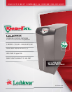
Knight
®
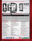
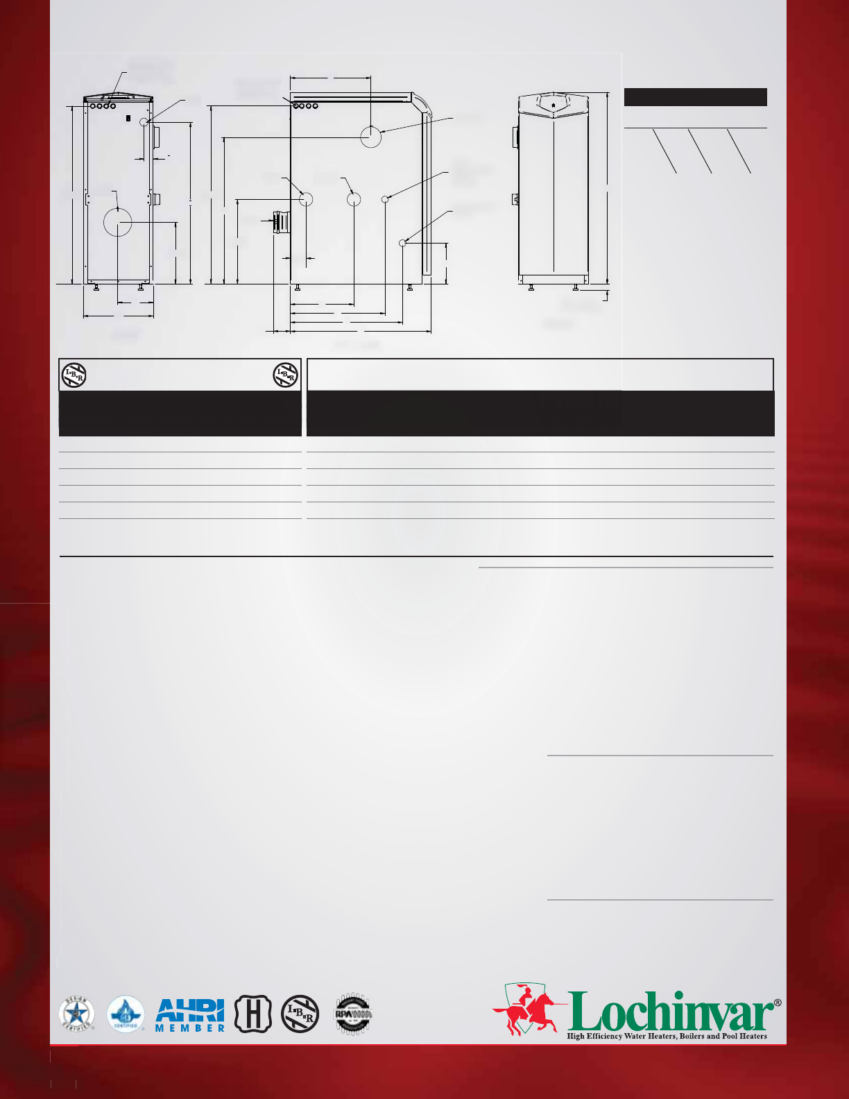
XL Boiler Dimensions and Specifications
Model Number Guide
KB N 700 M13
Model
Firing Controls
Natural Gas
Btu/hr Input
Input Net
Model Min Max Thermal Output I=B=R
Number MBH MBH Efficiency MBH MBH
KBN399 80 399 93.3% 372 324
KBN500 100 500 93.3% 467 406
KBN600 120 600 94.6% 567 493
KBN700 140 700 94.3% 660 574
KBN800 160 800 94.0% 752 654
A B C D E F G H I J K Gas Water Air Vent Shipping
Conn. Conn. Inlet Size Wt. (lbs.)
42-1/2” 15-1/2” 27-3/4” 3-3/4” 20-3/4” 21” 14” 34” 34” 2” 18-3/4” 1” 1-1/2” 4” 4” 280
42-1/2” 15-1/2” 31-1/4” 3-3/4” 25-1/2” 21” 14” 32-1/2” 36” 2” 18” 1” 1-1/2” 4” 4” 310
42-1/2” 15-1/2” 36-1/4” 3-3/4” 25” 21” 14” 36” 32-3/4” 5-1/2” 19-1/2” 1” 2” 4” 4” 340
42-1/2” 15-1/2” 40-1/4” 3-3/4” 29” 23” 17” 36” 32-3/4” 3-1/4” 23-1/2” 1” 2” 4” 6” 370
42-1/2” 15-1/2” 45-1/4” 3-3/4” 33-1/4” 23” 17” 36” 32-3/4” 3-1/4” 27-3/4” 1” 2” 4” 6” 405
Notes: Change ‘N’ to ‘L’ for L.P. Gas Model. No deration on L.P. models. Performance data based on manufacturer test results. 120 VAC /15 AMP circuit required.
All dimensions shown in inches.
Knight XL Heating Boiler Dimensions and Specifications
Knight XL Boiler,
Natural Gas,
700,000 Btu/hr input,
M13 firing controls
>
Mo
>
D
i
>
L
o
>
S
e
>
L
o
>
Ve
r
>
C
a
>
P
V
>
F
a
>
AS
M
>
A
S
>
G
a
>
1
6
>
H
i
>
On
/
>
Ad
j
>
Fl
o
w
>
In
le
>
F
l
u
e
>
Lo
w
>
50
>
Te
m
>
Ad
j
>
Co
n
>
Ze
r
>
10
(Se
KB
X-
0
300
I
n
put
Net
npu
tet
Mo
del
Mi
n
Max
Th
erm
al
Out
put
I=
B=R
odel a e al Output
Number MBH MBH Effici
enc
y MBH MBH
A
B C
D
E F
G
H I
J
A
B
C
D
E
F
G
H
I
J
K
night
XL
H
eating
B
oile
r
D
imensions and Specification
s
LEFT SIDE
FRONT
BACK
8"
39-1/2"
13-3/4"
18-3/4"
H
K
D
G
F
E
C
9"
A
1-1/4"1/4" -
ADJUSTABLE
AIR INLET
FLUE
LOW VOLTAGE
ELECTRICAL
CONNECTIONS
GAS
INLET
OUTLET
HEAT
EXCHANGER
DRAIN
3/4" NPT
CONDENSATE
DRAIN
FLUE
B
I
J
HIGH VOLTAGE
ELECTRICAL
CONNECTIONS
38-3/4"
3-1/2"
Patent # 7,506,617