


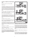
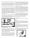
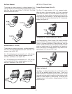
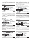
Set Point Demand
To generate a setpoint demand, a voltage between 24 V
(ac) and 230 V (ac) must be applied across the Setp / DHW
and Com Dem terminals (8 and 7) (FIG. 26). The DHW
MODE must be set to OFF.
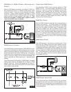
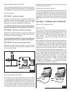
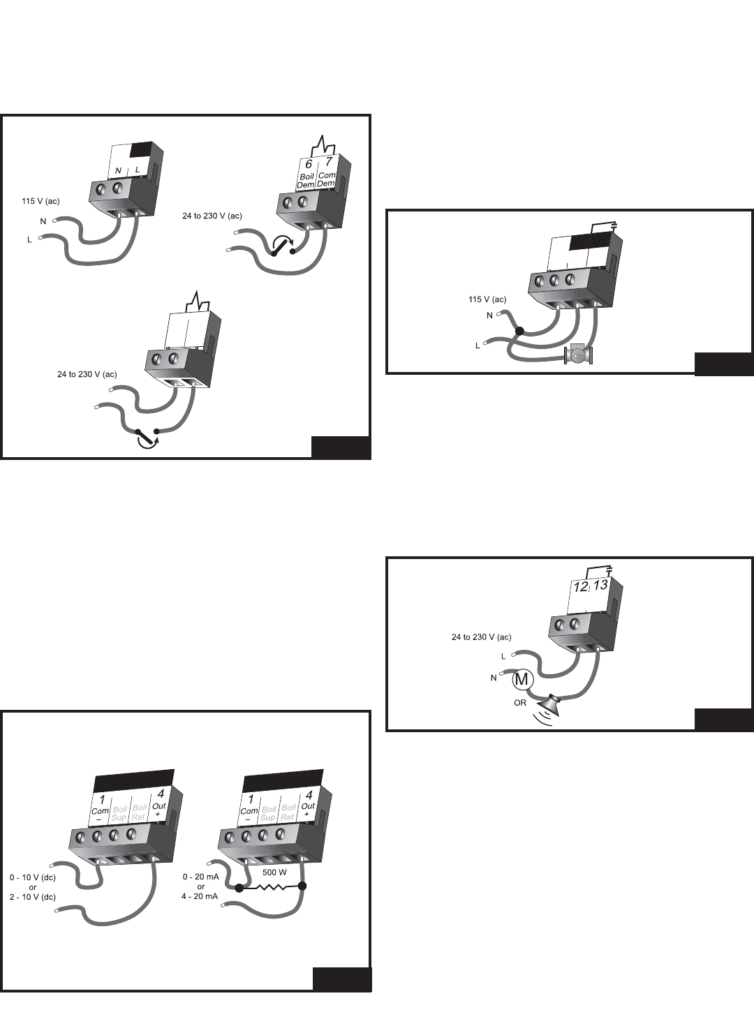
External Input (0 - 10 V dc)
To generate an external input signal, a voltage between 0
and 10 V (dc) must be applied to the Com - and Out + ter-
minals (1 and 4) (FIG. 27).
A 0 - 20 mA signal can be converted to a 0 - 10 V (dc) sig-
nal by installing a 500 ohm resistor between the Com -
and Out + terminals (1 and 4) (FIG. 27).
A 4 - 20 mA signal can be converted to a 2 - 10 V (dc) sig-
nal by installing a 500 ohm resistor between the Com -
and Out + terminals (1 and 4) (FIG. 27).
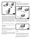
ƽ OUTPUT CONNECTIONS
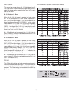
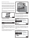
Primary Pump Contact (Prim P1)
The Prim P1 output terminal (11) is a powered output.
When the relay in the control closes, 115 V (ac) is provided
to the Prim P1 terminal (11) from the Power L terminal (10).
To operate the primary pump, connect one side of the pri-
mary pump circuit to terminal 11 and the second side of the
pump circuit to the neutral (N) side of the 115 V (ac) power
supply, see Figure 28.
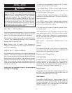
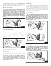
Combustion Air / Alarm Contact (C.A./Alarm)
The Combustion Air / Alarm Contact (C.A./Alarm) terminals
(12 and 13) (FIG. 29) are an isolated output in the control.
There is no power available on these terminals from the
control. These terminals are to be used as a switch to either
make or break power to the combustion air damper or
alarm. Since this is an isolated contact, it may switch a volt-
age between 24 V (ac) and 230 V (ac).
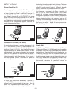
Relay 1 to Relay 9
The Relay 1 to Relay 9 terminals (14 and 15 to 30 and 31)
(FIG. 30) are isolated outputs in the control. There is no
power available on these terminals from the control. These
terminals are to be used as a switch to either make or break
power to a boiler stage or a boiler pump. Since this is an
isolated contact, it may switch a voltage between 24 V (ac)
and 230 V (ac).
10
Power
7
Com
Dem
Setp/
DHW
8
9
FIG. 26
Do Not Apply Power
Do Not Apply Power
–
+
–
+
FIG. 27
Prim
11
10
Power
L
9
P1
FIG. 28
C.A./
Alarm
FIG. 29
18