


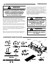
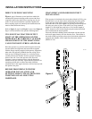
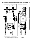
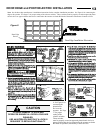

ITEM # PART# DESCRIPTION QUAN.
1 Operator Power Head 1
2 005031 3 Button St ation 1
3 30 Tooth Sprocket, 1” Bore, 1/4 Key 1
4 20 Tooth Sprocket, 1” Bore, 1/4 key 1
5 105193 Release/Hand Chain Wall Bracket 1
—— AR - As Required
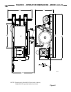
ITEM # PART# DESCRIPTION QUAN
6 100413 1/4” Square Key 2
7 006119 5/16-18 x 1 Square Head Set Screw 4
8 105323 Steel #80 Release Chain AR
9 100315 #3 Hand Chain - Precut to 26 Ft. 1
10 Drive Chain to Door Shaft, 4 Ft. 1
11 3 Piece Chain Connecting Link 1
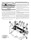
COMPONENT IDENTIFICATION LISTING
TO REDUCE THE RISK OF SEVERE
INJURY OR DEATH:
WARNING
• Install only on a properly operating and balanced
garage door. A door that is operating improperly
could cause severe injury. Have qualified service
personnel make repairs to cables, spring assemblies
and other hardware before installing the opener.
• Remove all pull ropes and remove, or make
inoperative, all locks (unless mechanically and/or
electrically interlocked to the power unit) that are
connected to the garage door before installing the
opener.
• Lightweight doors (fiberglass, aluminum etc.)
must be reinforced to avoid door damage. Check
the door manufacturer’s instruction manual for a
bracing procedure or the availability or a
Reinforcement Kit.
• Model AUJ and AUH are Commercial Vehicular
Door Operators and as such ARE NOT
recommended for pedestrian traffic. In
installations where it is known that pedestrians will
be nearby ensure a pedestrian door is available for
entrance and exit to the building. In addition YOU
MUST install an auxiliary entrapment protection
device (reversing door edge or photoelectric beam
device).
• Connect an auxiliary entrapment protection
device (reversing edge or photoelectric device across
the door opening). A device of this type is
STRONGLY ADVISED FOR ALL commercial
operator installations. An auxiliary entrapment
protection device is REQUIRED when the three
button control station is out of sight of the door or
any other automatic or manual control is used.
• Install the door operator at least 8 feet or more
above the floor if the operator has exposed moving
parts.
• Do not connect the opener to the source of power
until instructed to do so.
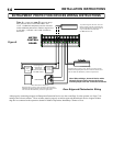
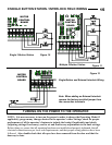
• Locate the control station:
a) within sight of the door,
b) at a minimum height of five feet above the
floor so small children cannot reach it,
c) away from all moving parts of the door, and
d) far enough away from the door, or positioned
such that the user is prevented from coming in
contact with the door while operating the
controls.
Do not overtighten the clutch adjustment to
compensate for a poorly working door.
Install the Entrapment Warning Placard next to
the control station in a prominent location.
All warning signs and placards must be installed
so they are visible in the area of the door.
After installing the opener, all safety features
must be tested for proper operation (see page 22).
For products having a manual release, instruct the
end user on the operation of the manual release.
5
IMPORTANT INSTALLATION INSTRUCTIONS!
READ AND FOLLOW ALL INSTALLATION INSTRUCTIONS!