


Page 2 of 4
P/N 190-104780 REV D
IMPROPER WIRING COULD CAUSE ELECTROCUTION OR DAMAGE TO CIRCUITRY.
FOLLOW LOCAL BUILDING AND ELECTRICAL CODES.
WARNING
WARNINGWARNING
WARNING
WARNING
WARNINGWARNING
WARNING
DO NOT USE RADIO CONTROLS ON COMMERCIAL DOOR OPERATORS UNLESS
PROPER ENTRAPMENT PROTECTION DEVICES ARE INSTALLED. CONSULT THE
MANUFACTURER OF YOUR OPERATOR FOR MORE DETAILS.
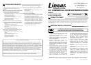
831 COMMERCIAL RECEIVER WIRING INSTRUCTIONS
The 831 receiver functions as a 3-button station. Three sets of isolated contacts are provided; normally open contacts for the
OPEN PUSHBUTTON (terminals #3 & #4); normally open contacts for the CLOSE PUSHBUTTON (terminals #5 & #6);
normally closed contacts for the STOP PUSHBUTTON (terminals #7 & #8). For special STOP circuit applications,
normally open contacts (terminals #8 & #9)
are available. Refer to Figure 1.
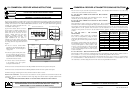
Typical 4-wire 3-button stations are wired as
shown in Figure 2. Number 18 gauge wire or
heavier must be used for wiring the control
stations and the 831 receiver to the door
operator. Smaller gauge wire may cause
operational problems, especially when
multiple 3-button stations are used. For
typical installations the 831 receiver is
mounted near the door operator, away from
any high voltage conduits or steel support beams.
For wiring, follow the steps below and refer to
Figure 3.
•
In the 831 receiver, connect STOP
terminal #7 to CLOSE terminal #6 and to
OPEN terminal #4. Use short lengths of
18 gauge wire.
•
In the door operator control panel, locate
the wire connecting the door operator to
the 3-button station COMMON. Note its
location and remove. Reconnect this wire
to terminal #8 in the 831 receiver.
•
In the 831 receiver connect terminal #7
to the terminal in the door operator
control panel identified above.
•
In the 831 receiver connect terminal #5 to the CLOSE pushbutton terminal in the door operator control panel.
•
In the 831 receiver connect terminal #3 to the OPEN pushbutton terminal in the door operator control panel..
•
Finish the wiring by connecting the 24 VAC to terminals #1 and #2 in the 831 receiver.
FOR 115 VAC UNIT ONLY: If the 831 receiver was ordered for 115 VAC operation it has a transformer mounted on the
circuit board. Connect 115 VAC to terminals #1 and #2. High voltage wires must be routed in a separate conduit from the
low voltage wires.
BEFORE APPLYING POWER, CHECK ALL CONNECTIONS AND INSTALL THE ANTENNA.
Figure 2 Figure 1
1 32 54 76 8 9
OPEN CLOSE STOPPOWER
CAUTION
24 VOLTS
AC ONLY
RADIO RECEIVER TERMINAL STRIP
STOP
CLOSE
OPEN
TERMINAL STRIP
TO OPERATOR
WALL PUSHBUTTON STATION
105113
Figure 3
105113
COMMERCIAL
STOP COM CLOSE
OPEN
OPERATOR RECEIVER
831
OPEN
STOP
CLOSE
WALL PUSH −
BUTTON STATION
1 2 3 4 5 876 9
DISCONNECT POWER TO RECEIVER AND DOOR OPENER BEFORE WIRING
PERMANENTLY TO PREVENT ELECTROCUTION.
WARNING
WARNINGWARNING
WARNING
Page 3 of 4
P/N 190-104780 REV D
The 831 receiver may be used with many different transmitters. The information below indicates how to set the coding
switches in the various transmitters and the 831 receiver.
I
F
YOU
ARE
USING
A
8831
OCS
-
ECONOMY
OR
831
STANDARD
TRANSMITTER
:
Exactly match all 8 code switches in the transmitter and receiver. The code
switches may be set in any random pattern of +, - and 0.
I
F
YOU
ARE
USING
A
8831C
OCS
-
ECONOMY
OR
733
STANDARD
TRANSMITTER
:
These transmitters are used to control up to 3 different doors. This is accomplished by setting the selector switch on the
transmitter to either A, B & C and setting the #6 coding switch in the 831 receiver .
Start coding by exactly matching all 8 code switches in the transmitter and the receivers. The code switches may be set in any
random pattern of +, 0 and - positions. Next, in receiver A, set code switch #6 to the + position; In receiver B set code
switch # 6 to the 0 position; In receiver C set code switch # 6 to the - position. The table to the right shows the switch
positions.
I
F
YOU
ARE
USING
A
639
STANDARD
TRANSMITTER
:
This transmitter is used to control up to 9 different
doors. This is accomplished by setting the selector
switch on the transmitter to either 1, 2, 3, 4, 5, 6, 7, 8 or
9 and setting the #7 and #8 coding switches in the 831
receiver.
Start coding by exactly matching all 8 code switches in
the transmitter and receivers. The code switches may be
set in any random pattern of +, 0 and - positions. Next,
in receiver 1, set code switch #7 to + and code switch #8
+; In receiver 2, set code switch #7 to + and code switch
#8 to 0. Continue setting the codes in the 831 receivers
as shown in the table.
I
F
YOU
ARE
USING
A
535
STANDARD
TRANSMITTER
:
This transmitter is used to control up to 27 different doors. This is accomplished by setting the selector switches to either A,
B or C and either 1, 2, 3, 4, 5, 6, 7, 8 or 9 and setting the #6, #7 and #8 coding switches in the 831 receiver.
Start coding by exactly matching all 8 code switches in the transmitter and receiver. Next, in receiver A1, set code switch #6
to +, set code switch #7 to + and code switch #8 to +; In receiver A2, set code switch #6 to +, set code switch #7 to + and
code switch #8 to 0. Continue setting the codes in the 831 receivers, using both tables shown above.
TRANSMITTER
A-B-C Selector
Switch Position
RECEIVER
Coding Switch
#6
A +
B 0
C -
TRANSMITTER
1 - 9 Selector
Switch Position
831 RECEIVER
Code Switch #7
831 RECEIVER
Code Switch #8
1 + +
2 + 0
3 + -
4 0 +
5 0 0
6 0 -
7 - +
8 - 0
9 - -
DISCONNECT POWER TO RECEIVER AND DOOR OPENER BEFORE WIRING
PERMANENTLY TO PREVENT ELECTROCUTION.
WARNING
WARNINGWARNING
WARNING
COMMERCIAL RECEIVER & TRANSMITTER CODING INSTRUCTIONS