


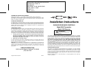
For remote installation the receiver may be mounted near the operator head on a
joist or the ceiling by using the mounting tab. Order Model 1092-06 adapter,
which permits connection between the operator terminal and the two-way lugs
on the receiver.
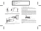
Slip on connectors at one end of the adapter connect to the flat side of each
spade lug on the receiver, and spade connectors at the other end connect to
the operator terminal. Connect the wires as follows:
(a) White wire to terminal “1” or “24v”
(b) Black wire to terminal “2” or “Relay”
(c) Red wire to terminal “3” or “Common” (“Radio Power”)
(d) Connect push button wires to terminal “1” and “2” (See Figure #2).
Where power for the radio receiver is not available from the operator order a
Model 1092-01 power transformer adaptor for connection between the
operator and the remote receiver.
ACCESSING THE CODE SWITCH
Using a small screwdriver, pry the rectangular hatch from the receiver for
access to the code switch. On the transmitter the entire front lower half of the
case is removable. Grasp the front lower half of the case near the bottom on
both sides and pull upward away from the transmitter, this will disengage the
lower end. Then pull down ward to remove the lower cover, this will expose both
the code switch and battery compartment. Set both switches to the code of your
choice, being sure both are set the same since a different setting of just one
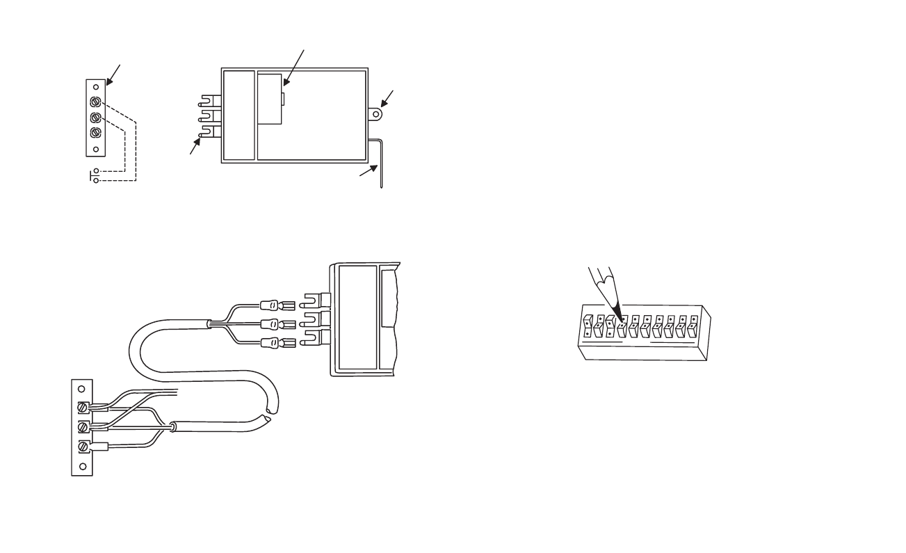
switch will prevent operation. The digital code is determined by the position of
10 small switches numbered 1 through 10 located in the receiver and
transmitter. Any combination of “on” or “off” positions can be selected by using
a pencil or ball point pen. (Note: The switches are in the “on” position when the
switch is depressed toward the number.) See Figure #3.
Once the codes have been set, check operation and reinsert the hatches.
TRANSMITTER INSTALLATION
The transmitter is completely self contained, including battery, and can be
operated while mounted in the car. It is supplied with a clip for attaching to the
sun visor, if desired. If the clip is used attach to the case by sliding it into the
recess provided on the back of the transmitter until the small dimples fit into the
holes in the clip.
CAUTION:
Keep the clip flat when pushing it into position so that is doesn’t
extend down into the case where it could touch the circuit board and cause
damage.
INSTR,INSTL,MC1090,GDO,RECEIVER
LINEAR P/N: 214961 A
INK: BLACK
MATERIAL: 20 LB. MEAD BOND
SIZE: 9.000" x 5.500"
SCALE: 1-1
SIDE 2 OF 2
OPERATOR TERMINAL
24 VOLT
RELAY
COMMON
1
2
3
WALL
BUTTON
2 - WAY LUGS
CODE SWITCH MATCH
MOUNTING TAB
ANTENNA
Figure 1
OPERATOR
TERMINAL
STRIP
TO WALL
PUSH BUTTON
SWITCH
White
Black
Red
White
Black
Red
Figure 2
1
2
3
1
2
3
4
5
6
7
8
9
10
Figure 3
OPEN