B-1
OPERATION
MINIFLEX
B-1
Read and understand this entire section before
operating your Miniflex.
SAFETY PRECAUTIONS
Always operate this equipment with the filters
installed and covers in place as these provide
maximum protection from moving parts and
insure proper vacuum operation and cooling air
flow.
-----------------------------------------------------------------------
RECOMMENDED USES
The Miniflex is a small, portable filtration unit designed
for light to medium duty weld applications and is used
for extracting and/or filtering fumes that are released
during the following welding processes:
• MIG/MAG solid wire (GMAW)
• MIG/MAG flux cored wire (FCAW)*
• Stick welding (SMAW)
• TIG (GTAW) welding
*For light flux-cored applications only.
Use of the product for extracting and/or filtering
fumes and/or gases that are released from the fol-
lowing processes is not recommended:
• Welding applications with intensive use of Tip Dip
(anti-spatter).
• Autogenic or plasma cutting spray/molten metal.
• Arc-air gouging.
• Welding that produces the release of a dense oil
mist.
• Paint spraying.
• Extraction of hot gases (more than 104° F, 40° C.)
• Extraction of aggressive fumes (such as acids).
• Grinding aluminum and magnesium.
• Flame spraying.
• Extraction of cement, saw dust, wood dust, etc.
• Extracting cigarettes, cigars, tissues and other
burning particles, objects and acids.
• Any dangerous situations where there is a risk of
an explosion or fire.
Note: The Miniflex does not filter any shielding
gases. Gases pass through the filter. Miniflex
used with optional carbon filter may reduce
vapors and gases.
OPERATING INSTRUCTIONS
The Miniflex provides enough suction for one fume
gun or small suction nozzle. Do not attach more than
one fume gun or suction nozzle to the Miniflex unit.
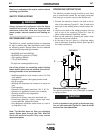
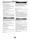
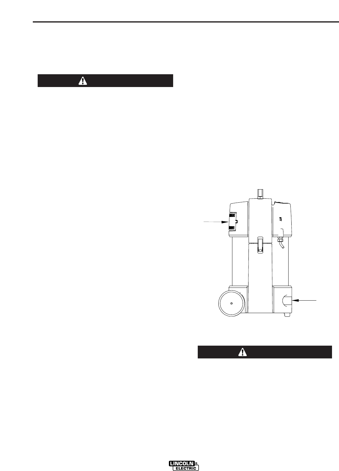
1. Connect the extraction hose at one side to the air
inlet of the machine (Figure B.1, Item A) and at the
other side to the welding torch or small suction noz-
zle.
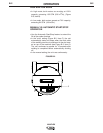
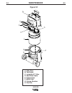
2. Lay the work cable of the welding machine into the
slot on top of the machine (Figure B.2, Item A)
(when using Automatic Start/Stop mode).
3. Start up the machine by pressing the switch, locat-
ed on the side of the machine.
4. At the top of the unit, there is a High/Low button
and an Automatic Start/Stop Button (see Page B-2
for further instructions).
FIGURE B.1
Recommended Positioning: Upright
For optimal performance, unit is designed to operate
in upright position.
If unit is operated in an upright or horizontal posi-
tion, air inlet and outlet (Figure B.1, Items A and B)
must be free from obstruction.
WARNING
A
B
CAUTION


