OPERATION
TEC Connector
06_03 TCM-39032 7
CHAPTER 2
TEC Connector
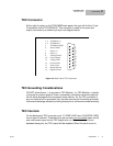
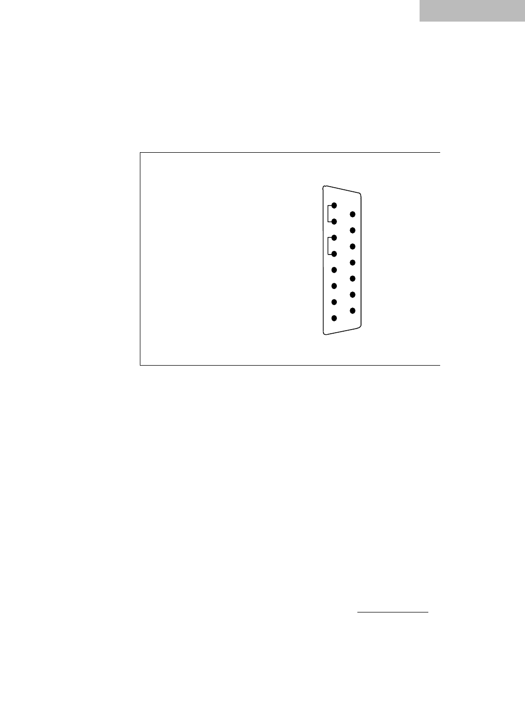
At the right of center, on the TCM-39032 back panel, the user will find the 15-pin
D-connector for the TEC MODULE. This connector is used for the input and
output connections, as shown by the pin-out diagram below.
Figure 2.2 Back Panel TEC Connector
TEC Grounding Considerations
DO NOT allow Sensor (-) to connect to TEC Module (-) or TEC Module (+) directly
or through a common ground. Even a momentary connection when the output is
off will cause damage to the instrument and/or device. For the TEC connector, if
any one terminal pin is grounded, then no other terminal pin should be grounded.
Instrument damange caused by shorting these pins is not covered under warranty.
TEC Interlock
On the back panel TEC connector, pins 13 (TEMP LIMIT) and 15 (DIGITAL GND)
form a type of interlock. These two pins are normally not connected
(open circuit)
and must remain open for the TEC output to be on. If there is a short circuit
between these pins, the TEC output will be disabled. When this short circuit is
1
2
3
4
5
6
7
8
9
10
11
12
13
14
15
1, 2 TE Module (+)
3, 4 TE Module (-)
5 TE Module Shield
6 Sensor Shield
7 Sensor (+)
8 Sensor (-)
9 Analog Ground
10 Control Signal
11 Voltage Limit
12 Current Limit
13 Temp. Limit
14 Booster Present
15 Digital Ground


