


r
READ AND UNDERSTAND THESE INSTRUCTIONS BEFORE INSTALLING FIXTURE
Thisfixtureisintendedforinstallationinaccordancewiththe National
Electrical Code and load regulations.
To assure full compliancewithlocalcodesandregulations,checkwithyourlocalelectricalinspector
before
installation. Toprevent electrical shock, turnoff electricity at fuse box before proceeding.
Retain these instructions for maintenance reference.
INSTRUCTION SHEET NO.
IS:6079
0493
Page 1 of 2
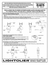
INSTALLATION FOR AITACHING EXTENSION WAND SLOPED CEILINGS ADAPTER
TO LYTESPAN TRACK. FOR USE WITH LYTESPAN” TRACK SYSTEMS ONLY
Extensionwandslopedceilingadaptercanbe mountedonanyBasic,Advent MultipointorMonopointTrackontailings from 0° to 90° (vertical).
Notfor usewithLytespota with attachmentfitting 7589.
1.
Grasp TOP FITTING at topof ADAPTER and insertit intothe LYTESPAN TRACK. The LOCKING LEVER must be on the same side of the track as the BEAD.
(see Fig. 1.)
2. Rotate the TOP FI’ITING W’ clockwise, (See Fig.2), untilLOCKING LEVER snaps and locksinplats. (See Fig.3.) Do notrotate adapter from LOWER FllllNG.
3. Loosen KNOB and set the lower haffof the ADAPTER to a vertical positionand tighten KNOB. (Fig, 4)
4. To Remove Depress LOCKING LEVER; then rotate TOP FllllNG 90° counter-dockwke. Do not rotatewand from LOWER FITTING,
BEAD
LOCKING
LEVER
FIG. 1
LVTESPAN
TRACK
FITTING
c
-u
CLOCKWISE
FIG. 2
!l-
ri
FIG. 3
NG
L
‘“WERF’”’N
I
I I
FIG. 4
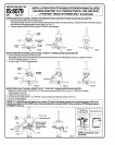
INSTRUCTIONS
FOR CONVERTING FITTING TO OPERATE ON
2 CIRCUIT TRACK SYSTEMS
BRASS CONTACT
See Fig.5, BRASSCONTACT canbe raisedorlowered,Brokenlineindicatespositionfor1circuit
trackorlowercircuitof2 circuittracksystem.
L::;;:G
To mnverf attachment FllTING for uppercircuitof2 circJJittrack, raise BRASS CONTACT tohigh
positionby Ming CONTACT as high as stop f.wrnits and CONTACT clicksintoplace.
FIG. 5
INSTRUCTIONS FOR AllACHING EXTENSION WAND TO EXTENSION WAND SLOPED CEILING ADAPTER
1.
Insert the WAND FllllNG into the LOWER FllllNG.
The LOCKING LEVER must be on the same side as the bead located at the bottom of the LOWER FllTING (See Fig. 6.) Rotate the WAND FllllNG
90° clockwise until LOCKING LEVER snaps and locks in place. (See Fig. 6,7, & 8).
2, To remove, depress LOCKING LEVER and rotate FllllNG 90° counterclockwise.
$
/-R/la
BEAD BRASSCONTACT
“OWN
LOCKING_
_ WAND
CLOCKWISE
LEVER
FllTNG
1
FIG. 6
FIG. 7
i
FIG. 8