


I
v
INSTRUCTION SHEET NO.
1S:6074
INSTALLATION FOR AITACHING EXTENSION WAND TO
LYTESPAN TRACK
RO193 Page 2 of 2
FOR USE WITH LYTESPAN@TRACK SYSTEMS ONLY (Cent’d)
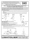
INSTRUCTIONS FOR ATTACHING LOW VOLTAGE LYTESPOT TO LYTESPAN” WAND
1,
insert the FIXTURE FITTING into the WAND SOCKET,
The LOCKING LEVER must start on the same side as the bead located at the bottom of the WAND SOCKET (See Fig. 8,) Rotate the FIXTURE
FllliNG 90° clockwise. (See Fig. 8,9, & 10),
2. To remove, rotate FllllNG 90° counterclockwise,
.
WAND –
SOCKET
r-l
n
BEAD
IMPRG _
CLOCKWISE
( @
m
t\
{
f“ 1
\
FIG. 8
FIG. 9
FIG. 10
INSTRUCTIONS
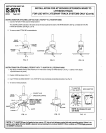
FOR AllACHING LYTESPOF WITH “T” ADAPTOR TO LYTESPAN@ WAND
1.
Align BEAD on WAND SOCKET with GROOVE in FITTING before inserting into WAND SOCKET, see Fig. 11, (BEAD is NOT aligned
a potential hazard may result,)
2, Position LEVER as shown in Fig. 11.
3, Insert FllTING into WAND SOCKET. Turn LEVER 90° to make mechanical and electrical connection. See Fig. 12.
4. To remove: reverse procedure.
‘4
CONTACT HUB
WAND
SOCKET
.._~
$
GROUNDING SPRING
BEAD _
REMOVE CORK AND
._ ————
PAINT (IF PRESENT)
-“
*
FROM THIS AREA
-“
;\t:;UDIE PROPER
=... LOCK
GASKET
-.-J
1
3
GROOVE
\
RELEASE
LEVER
FITTING
FIG. 11
FIG. 12
FIG. 13
NOTE:If “T” ADAPTOR has a full gasket on top, remove 1/2” strip of cork between contact hub and grounding spring. If there is no
gasket, and a tighter fit to the WAND is desired, remove backing from enclosed GASKET. When centered on FllllNG apply pressure
on GASKET to secure it.
\
—