


READ AND UNDERSTAND THESE INSTRUCTIONS BEFORE INSTALLING FIXTURE
This fixture is intended for installation in accordance with the National Electrical Code and local regulations. To
assure full compliance with local codes and regulations, check with your local electrical inspector before
installation. To prevent electric shock, turn off electricity at fuse box before proceeding.
Retain these instructions for maintenance reference.
INSTRUCTION SHEET NO.
IS:4X4
B0502
Page 2 of 2
A COMPANY
631 Airport Road, Fall River, MA 02720
90
°°
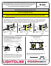
B. ADJUST FIK
Set FIK so that bottom edge is flush to, or
recessed 1/8” above finished ceiling (Fig. 8).
Final vertical adjustment may be made by means of
ADJUSTMENT SCREWS on inside of FIK.
C. CLOSE-IN
Close-in and finish ceiling as required.
D. INSTALLATION OF REFLECTOR TRIM
1. Squeeze both TORSION SPRINGS and insert ends into
EMBOSSED SLOTS.
2. Push REFLECTOR TRIM up into FIK until flange is seated firmly
against ceiling surface.
**Care and Maintenance of “Alzak” REFLECTOR TRIM finish:**
If handling of REFLECTOR TRIM with anodized or Alzak finish is required, the
use of clean white or plastic film gloves is recommended to avoid fingerprints.
Anodized or Alzak surfaces can be cleaned by the following methods:
1. Wipe off with a soft, clean, dry, lint-free cloth.
2. Wipe off with a soft clean cloth dampened in mild detergent solution.
Rinse, then wipe dry with lint-free cloth or paper towel.
3. Wipe off with a clean cloth dampened with a solution of wetting agent and
water (such as 2 oz. Per gallon “Pluronic L62-LF” by Wyandotte Products).
Wipe dry.
4. Use a liquid wax such as Glass Wax. Avoid gritty cleaning agents.
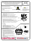
E. RE-LAMPING
1. Turn off power
2. Pull REFLECTOR TRIM down until ends of TORSION
SPRINGS reach EMBOSSED SLOTS.
3. Squeeze TORSION SPRINGS to disengage from EMBOSSED
SLOTS, and remove REFLECTOR TRIM.
4. Replace lamp (Do not exceed maximum wattage marking).
5. Replace REFLECTOR TRIM.
F. BALLAST REPLACEMENT
1. Make sure AC power is OFF at fuse-box.
2. Remove REFLECTOR TRIM & lamp(s) (See E.).
3. Undo WINGNUT(s) and remove UPPER REFLECTOR.
4. Remove NUTS that secure BALLAST PLATE to HOUSING.
5. Partially remove BALLAST PLATE from HOUSING.
6. Disconnect wire leads from BALLAST push-in terminals.
(Insert pin or paper clip in RELEASE SLOT, Fig. 11)
7. Remove BALLAST from BALLAST PLATE, and install new
BALLAST.
8. Insert wire leads into BALLAST. Follow wiring diagram on
BALLAST.
9. Reattach BALLAST PLATE, UPPER REFLECTOR, lamp(s),
and REFLECTOR TRIM.
BALLAST
BALLAST
PLATE
FIG. 12
FIG. 11
RELEASE
SLOT
UPPER
REFLECTOR
NUTS
HOUSING
WINGNUT
TORSION
SPRING
EMBOSSED
SLOT
REFLECTOR
TRIM
FIG. 10
BALLAST
PLATE
ADJUSTABLE
MOUNTING
BRACKET
FINISHED
CEILING
FLUSH TO CEILING OR
UP TO 1/8” RECESSED
ADJUSTMENT
SCREWS
FIG. 8
FIK
Base of FIK is provided with a
hole pattern (Fig. 9) to assist with the
alignment of multiple FIK’s. This hole
pattern will facilitate the use of laser
beams, plumb lines, etc.
FIG. 9