


Instruction Sheet Number IS:48021
Page For Assembly and Installation of Soli ADA Series Wall/Ceiling Mounted T-5 Fluorescent
Lightolier a Genlyte Thomas Companywww.lightolier.com
631 Airport Road, Fall River, MA 02720 (508) 679-8131 Fax (508) 674-4710
We reserve the right to change details of design, materials and finish.
© 2003 Genlyte Thomas Group LLC (Lightolier Division) A0403
2 of 2
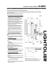
E. ELECTRICAL CONDUIT MOUNTING ( Fig. 3 )
1. Insert electrical conduit connector through CONDUIT
PLATE (supplied) and secure with LOCK NUT (by
others).
2. Pull supply wires through center hole in BACK PLATE.
Align BACK PLATE and mark holes for DRYWALL
ANCHORS (supplied), screw DRYWALL ANCHORS
into wall.
3. Secure BACKPLATE to CONDUIT PLATE and
DRYWALL ANCHORS with screws provided.
4. While supporting BALLAST HOUSING, Make electrical
connections: Black lead or lead without tracer marks to
hot (Black) supply lead; White lead or lead with tracer
marks to neutral (White) supply lead. Uninsulated wire
is a ground wire and must be connected to grounding
terminal or ground lead. Use WIRE NUTS.
5. Carefully push connections back into the BALLAST
HOUSING.
6. Align tabs at top of BALLAST HOUSING with slots on
BACK PLATE, snap in and push housing flush with
wall.
CAUTION: MAKE CERTAIN THAT NO WIRES ARE
PINCHED BETWEEN BACK PLATE AND FIXTURE
BODY.
7. Insert ALLEN HEAD SCREW (provided) into hole at
bottom of BALLAST HOUSING and secure BALLAST
HOUSING to BACK PLATE.
For DIFFUSER & FRONT COVER attachment
proceed as per Sections B & C on first page of
these instructions.
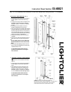
F. 2-FOOT SOLI ELECTRICAL CONDUIT MOUNTING
Note: 2 foot version cannot be wired through the center
hole but must use one of the KNOCK OUT HOLES.
(Fig. 4 )
1. Insert electrical conduit connector through CONDUIT
PLATE (supplied) and secure with LOCK NUT (by
others).
2. Select KNOCK-OUT HOLE on BACK PLATE. Pull
supply wires through center hole in BACK PLATE.
Align BACK PLATE and mark holes for DRYWALL
ANCHORS (supplied), screw DRYWALL ANCHORS
into wall. Proceed as per items 3 through 7 above.
For DIFFUSER & FRONT COVER attachment
proceed as per Sections B & C on first page of
these instructions.
Figure 4
Figure 3