


[ . [~sTRLJcTloNsj+EETNoo I
—.-. — L— .. .
OCIAGONAL OUTLET BOX y
~OUTLZT BOX COb’ER
IIS:$44224, ,
o“
— -------...—
“io94
.
PAGE 2 OF 2
I
o
\
1
,_.
..——. .—
.—
BACKPLATE”
ASSf MBLY
CfU/SWITCH OUTLET BOX - \
,, ,..
3.
.4.
MOUNTING
1
\
HOLCS
0
0
.
.
0
0
~AcKpuTE , -. . .. .
. ~—. ..— ..—
——-
.-. —- . . ..
AS LCUSLYr ---
~~lGUR~ Z<i
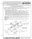
pcsition BACKpLATE AS S~BLY centered over OUTLET BOX. Use a leVel
placed on top of fixture. Once fixture is level, use MOUNTING
HOLES as a template and mark drill locations (see figure 2) .
Usin~ all MOUNTING HOLES in BACKPLATE ASSEMBLY, secure to wall
!
I
I
using wood screws, toggle bolts,
or alternate fasteners (not pro-
vided) depending on wall material. Note: care must be taken to
insure that OUTLET BOX is completely covered.
F.OR HORIZONTALLY MOUNTED RECTANGULAR GEM OR SWITCH OUTLET BOXES:
1. Make,wiring connections per instruction provided in’istep 211above.
2.
PositIon BACKPLATE ASSEMBLY per instruction provided in’lstep 3’1.
3.
Mount BACKPLATE ASSEMBLY per instruction provided inf’step 4“
above.. Note:
where fixture is mounted vertically, gem or switch
outlet box must be also installed vertically.
COVERI?LATE MOUNTING PROCEDURE:
1;. Remcve THREADED KNOBS that secure END COVERS to COVER PLATE. Re-
mcve END COVERS and set aside with THREADED KNOBS.
2; Install COVER PLATE onto THREADED STUDS (pressing firmly to
compress the GROUNDING CLIP) on BACKP’LATE ASSZMBLY. ~se_ extreme
care to not pinch wires between parts. (Note: when installing fix-
ture horizontally, observe
llTHIS EDGE UP” marking on COVERP-LATE
to insure proper orientation).
Secure COVER PLATE to BACKPLATE
ASSEMBLY by threading CAPSCREWS anto MOUNTING STU9S(see figure 1)
3. Install recommen~ed lamps. Caution:
maximum wattage marked on the
f~xture must not be exceeded.
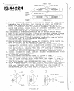
GLASS DIFFUSER INSTALLATION:
1. Position GLASS DIFFUSER as shown in figure 3, step 1.
2. Move GLASS DIFFUSER towards COVER PLATE until UPPER and LOWER
TABS on GLASS DIFFUSER touch COVER PLATE (see figure 3, step 2) .
3.
Gently slide GLASS DIFFUDER in a downward direction until UPPER
TABS fullv en~aae into HOLDER BRACKETS (see fiqure 3, step 3) .
4.
While sup~ort~n~ GLASS DIFFUSER,
install END COVERS onto THREADED
STUD on COVER PLATE.
Secure END COVERS by installing THREADED
KNOB onto THREADED STUD. Note:
ENDCOVERS that are closed-off on
one side are used on either end of fixture to close-off the _
HOLDER BRACKETS on the very ends (see figure 3, step 3) ..
—
o
1
/
7
“f
/’
+$
i*\
I
.
‘m–—-––-’-”” ““” - —
w
r--
VII
LOWER
/
.TABS
)
‘“-
GLASS
L<-
OIFFUSZR
COVER PLATE
–FIGURE 3–
CD
HOLDER BRACKCT
“/
ENO COVER
—
B<
,—
THREAOED.
KNOB
.
r
.-
i’,
(=
‘