


READ AND UNDERSTAND ALL TRACK, CONNECTOR, FEED-IN-KITS, AND ACCESSORY
INSTRUCTION SHEETS BEFORE INSTALLING ANY PROSPEC
®
TRACK ITEM.
This fixture is intended for installation in accordance with the National Electrical Code and local or Federal
code specifications. To assure full compliance with codes and regulations, check with your local electrical
inspector before installation. To prevent electrical shock, turn off electricity at fuse box before proceeding.
Retain these instructions for maintenance reference.
LIGHTOLIER a GENLYTE company.
631 Airport Road, Fall River, MA 02720
®
INSTRUCTION SHEET NO.
IS:26060
0597 Page 1 of 2
END FEED AND FLOATING CANOPY MOUNTING KIT - FLUSH AND STANDOFF VERSIONS
FOR USE WITH PROSPEC
®
SURFACE MOUNT TRACK SYSTEMS ONLY
END FEED MOUNTING INSTRUCTIONS
(Flush 26060WH, BK and Standoff 26061WH, BK)
Mounting the CANOPY at the end of FEED TRACK or directly above
a FEED CONNECTOR.
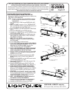
1. Mark CENTER LINE for TRACK through CENTER LINE of OUT-
LET BOX.
2. NOTE: The CANOPY mounts to a 3 or 4” OCTAGON OUTLET
BOX. The MOUNTING HOLES of the OUTLET BOX should be at
45° to the longitudinal axis of the TRACK. (Fig. 1)
3. Remove the KNOCK OUT PLATE from the FEED TRACK or
CONNECTOR (retain the SCREW). (Fig. 2)
4. Prepare TAB on the PLATE ASSEMBLY as follows:
• FEED TRACK: DO NOT BREAK ANY TAB. (Fig. 2)
• POWER EXTENSION, IN-LINE, “T”, AND “X” CONNECTORS:
BREAK THE 90° TAB OFF THE PLATE ASSEMBLY. (Fig. 3)
• “L” CONNECTOR: BREAK THE 90° TAB AND THE STRAIGHT
TAB FROM THE PLATE ASSEMBLY. (Fig. 4)
5. Attach the PLATE ASSEMBLY onto the FEED TRACK or
CONNECTOR using the SCREW. (Fig. 2 & 3)
6. Mount the TRACK to the ceiling (see instruction sheet
IS:26000 provided with the TRACK) passing the wires through
the center of the PLATE ASSEMBLY.
7. Rotate the PLATE ASSEMBLY until the SLOTS are in-line with
the MOUNTING HOLES on the J-BOX.
8. Secure the PLATE ASSEMBLY to the J-BOX using the THIN
HEAD SCREWS. (Fig. 5)
9. Attach the GROUND WIRE on the CANOPY PLATE to the
GROUND LEAD or GROUND TERMINAL in the J-BOX. (Fig. 5)
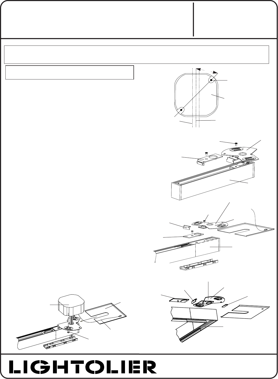
10. WHEN USING THE FLUSH CANOPY 26060WH/BK.
Slide the CANOPY PLATE between the CONNECTOR and
CROSS BAR on the PLATE ASSEMBLY. For added security of
CANOPY PLATE: Drill a hole in CANOPY PLATE and secure to
ceiling with a screw.
11. WHEN USING THE STANDOFF CANOPY 26061WH/BK
Slide the CANOPY PLATE between the CROSS BAR and NUT
on the PLATE ASSEMBLY. Rotate the NUT to secure the
CANOPY PLATE against the ceiling. (Fig. 8)
NOTE: THE CROSS BAR MUST COVER THE SLOT IN
THE CANOPY PLATE AFTER ASSEMBLY.
12. Follow the instructions for wiring on the instruction sheet
included with the “FEED TRACK” or “CONNECTOR”.
CAUTION: TURN OFF POWER AT FUSE BOX BEFORE
INSTALLING THE CANOPY KIT
POWER EXTENSION
CONNECTOR
PLATE
ASSEMBLY
SCREW
90 ° TA B
KNOCK OUT
PLATE
FIG. 2
FIG. 3
PLATE
ASSEMBLY
SCREW
KNOCK OUT
PLATE
FEED TRACK
FIG. 4
STRAIGHT
TA B
PLATE
ASSEMBLY
90 ° TA B
KNOCK OUT
PLATE
“L” CONNECTOR
CANOPY
PLATE
GROUND
WIRE
THIN HEAD
SCREW
J-BO X
FIG. 5
CROSS BAR
CROSS BAR
45 °
TRACK UNIT
LONGITUDINAL
TRACK
OUTLET BOX
OUTLET BOX
MOUNTING HOLE
FIG. 1