


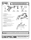
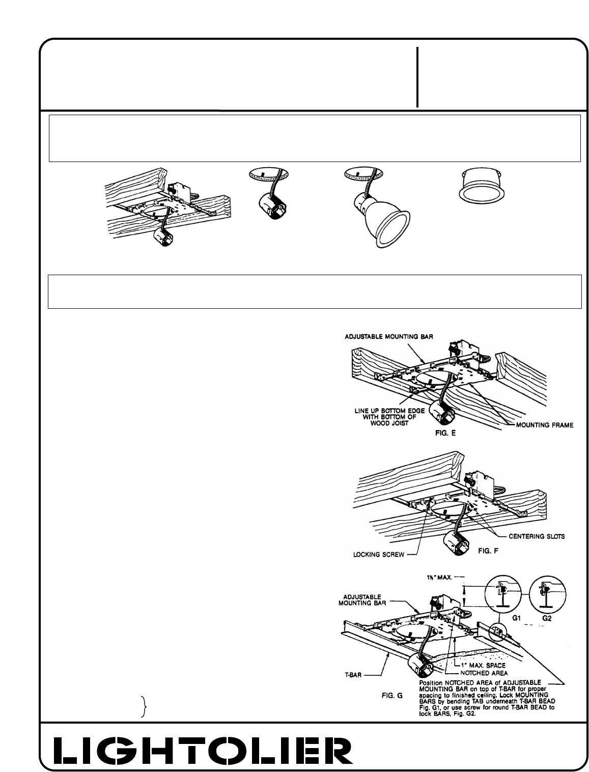
1. FRAME-IN (FIG. A)
Fasten MOUNTING FRAME to wood joist. Line-up bottom edge of
ADJUSTABLE MOUNTING BAR with bottom of wood joist (Fig. E). Wire to
supply leads. White fixture lead to neutral supply lead. Black fixture lead
to hot (120V) supply lead. Bare fixture wire to supply ground. Use
wirenuts (local hardware items). Place all electrical connections in the J-
BOX. Attach J-BOX COVER onto J-BOX. (Use built-in Cable Clamp in J-
BOX for non-metallic sheathed cable (Romex) or armored cable (BX).)
NOTE:
1. ADJUSTABLE MOUNTING BARS are pre-assembled on long side
of MOUNTING FRAME for rigidity and ease of installation (Fig. E).
MOUNTING BARS must be removed and installed on narrow side
of MOUNTING FRAME if required. Locking screws are provided to
lock frame in a desired position. (Fig. F)
2. MOUNTING BARS can be extended to 24”. The MOUNTING
FRAME can be mounted off-center. CENTERING SLOTS are provid--
ed as guides to align adjacent frames.
3. For suspended ceilings, make certain that bottom of MOUNTING
FRAME is no higher than 1” above ceiling line and notched area
of ADJUSTABLE MOUNTING BARS are positioned on top of
T-BAR (Fig. G).
2. CLOSE-IN (FIG. B)
Install plasterboard or other dry type ceiling. Hole in board can be cut
either on floor or after the board is secured in the ceiling. Use MOUNT-
ING FRAME opening as cutting guide (make sure ROTO CLIPS are rotated
out of hole area). ROTO CLIPS can only be rotated counter-clockwise. A
lanced stop detail is provided to prevent ROTO CLIPS from rotating clock-
wise. This detail allows easy removal of REFLECTOR TRIM by rotating
TRIM counterclockwise and permits installing REFLECTOR TRIM tightly
against the ceiling surface by rotating TRIM clockwise after pushing
TRIM into ceiling.
NOTE: For wet plaster ceiling, use Plaster Ring Accessory (order sepa-
rately): No. 1960 for 1002P1 Frame-In Kit; No. 1961 for 1102P1 Frame-In
Kit.
3. SNAP-ON (FIG. C) SEE SEPARATE REFLECTOR TRIM
4. PUSH-UP (FIG. D) INSTRUCTION SHEETS.
®
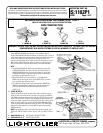
READ AND UNDERSTAND THESE INSTRUCTIONS BEFORE INSTALLING FIXTURE.
This fixture is intended for installation in accordance with the National Electrical Code and local or Federal
code specifications. To assure full compliance with codes and regulations, check with your local electrical
inspector before installation. To prevent electrical shock, turn off electricity at fuse box before proceeding.
Retain these instructions for maintenance reference.
INSTRUCTION SHEET NO.
IS:1102P1
A0403 Page 1 of 2
INSTALLATION PROCEDURE FOR FRAME-IN KIT 1102P1
(MAY BE USED FOR EITHER 7•11 OR LYTECASTER TRIM)
NEW CONSTRUCTION
LIGHTOLIER a GENLYTE THOMAS company.
631 Airport Road, Fall River, MA 02720
U.S. PATENT NO. 4,039,822
OTHER U.S. AND FOREIGN PATENTS PENDING.
FIG. A
1. FRAME-IN
FIG. B
2. CLOSE-IN
FIG. C
3. SNAP-ON
FIG. D
4. PUSH-UP
WARNING-(RISK OF FIRE) DO NOT INSTALL INSULATION WITHIN 3 INCHES OF FIXTURE SIDES OR WIRING
COMPARTMENT, NOR ABOVE FIXTURE IN SUCH A MANNER TO ENTRAP HEAT.