


..
●
READ AND UNDERSTAND THESE INSTRUCTIONS BEFORE INSTALLING FIXTURE
INSTRUCTION SHEET NO,
“his fixture is intended for installation in accordance with the National Electrical Code and local
emulations. To assure
full compliance with local codes and regulations, check with your local electrical
mpector before installation. To prevent electrical shock, turnoff electricity at fuse box before proceeding.
IS:8629
Retain these instructions for maintenance reference.
R0992
Page 1 of 2
INSTRUCTIONS FOR INSTALLATION OF LYTEDROP FIXTURE
FOR USE WITH 8600 SERl~S POWER JACKS ONLY
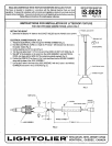
SETTING THE HEIGHT
POWER JACK ENTRY
1.
Determine the distance “A” between the SOCKET HOLDER and the POWER JACK ENTRY.
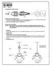
ELECTRICAL CONNECTIONS (FIG. 2 &3)
1. Thread the ELECTRICAL CORD through the WIRING CHAMBER (Fig. 2).
2. Knot the ELECTRICAL CORD so a length of (“A” minus 1 1/4”) remains from the knot to
the socket holder (Fig. 2).
STEM BUSHING
3. Cut the electrical cord 2“ from knot (Fig. 2).
4. Trim the outer jacket back 1 1/2” from the end of the CORD. DO NOT CUT WIRE (Fig. 2).
5. Strip 3/8” of the insulation on the wires from the JACK ASSEMBLY and ELECTRICAL .~
CORD. Join them with the WIRE NUTS provided (no polarity needed) (Fig. 2).
6. Position the WIRE NUTS as shown in Fig. 3 and insert them into the WIRING CHAMBER
along with the base of the JACK ASSEMBLY.
7. Lineup the 2 holes in the base of the JACK ASSEMBLY with the 2 holes in the WIRING
CHAMBER and screw in the 2 SCREWS (Figs. 2).
ELECTRICAL CORD
SOCKET HOLDER
FIG. 1
WIRE NUT
I!!
1 ‘
SCREW
SOCKET
r
-ti-;jl~~ ~
R3
HOLDER
+=
ELECTRICAL
COR
--::~-
----- —----- --
--- ---—- ---
2
3
“
WIRINGCHAMBE
“A” MINUS1 1/4
FIG. 2
1-B c> 1“1
T<> LIE la ER’AHN!WR%IU’::