


Lightolier a Genlyte Thomas Company www.lightolier.com
631 Airport Road, Fall River, MA 02720 • (508) 679-8131 • Fax (508) 674-4710
We reserve the right to change details of design, materials and finish.
© 2003 Genlyte Thomas Group LLC (Lightolier Division) • D0104
Job Information Type:
Narrow Spot Reflector - with 70W ED17 Master Color Ceramic Metal Halide Philips Protected (Clear) Lamp for Open Luminaires
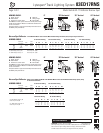
AIMING ANGLE: 0° Horizontal Aiming 30° Horizontal Aiming 30° Vertical Aiming 45° Vertical Aiming
DFC L W
DC FC L W
DC FC L W DC FC L W
Beam Spread
CBCP
Rated
(To 50% CBCP) Life (Hrs.)
12’ 382 1.7’ 1.7’
16’ 215 2.2’ 2.2’
20’ 137 2.8’ 2.8’
24’ 95 3.4’ 3.4’
10’ 5.8’ 357 1.9’ 1.6’
12’ 6.9’ 248 2.2’ 1.9’
20’ 11.5’ 89 3.7’ 3.2’
25’ 14.4’ 57 4.7’ 4.0’
5’ 8.7’ 275 2.8’ 1.4’
6’ 10.4’ 191 3.4’ 1.7’
10’ 17.3’ 69 5.7’ 2.8’
12’ 20.8’ 48 6.8’ 3.4’
8’ 8’ 304 2.2’ 1.6’
10’ 10’ 194 2.8’ 2.0’
16’ 16’ 76 4.5’ 3.2’
20’ 20’ 49 5.6’ 4.0’
54,959 10,000
8˚ X 8˚
For 50W: Multiply values by .68 Rated Lamp Life 10,000
For 100W: Multiply values by 1.5 Rated Lamp Life 12,500
Lytespan
®
Track Lighting System 83ED17RNS
Page 2 of 2 Metal Halide ED-17 Reflector Narrow Spot
AIMING ANGLE: 0° 30° Horizontal 30° Vertical 45° Vertical
L Beam Length D Distance
W Beam Width A Aiming Angle
C Distance to center beam FC Footcandles
L and W are the outer points where the candle power drops
to 50% of the maximum. FC are the initial footcandles at the
center of the beam.
Lamp data shown is typical. Consult lamp manufacturers for
availability and performance.
Narrow Spot Reflector - When used in 8307U and 8317U with 70W ED17 Master Color Ceramic Metal Halide Philips (Clear) Lamp
for Enclosed Luminaires
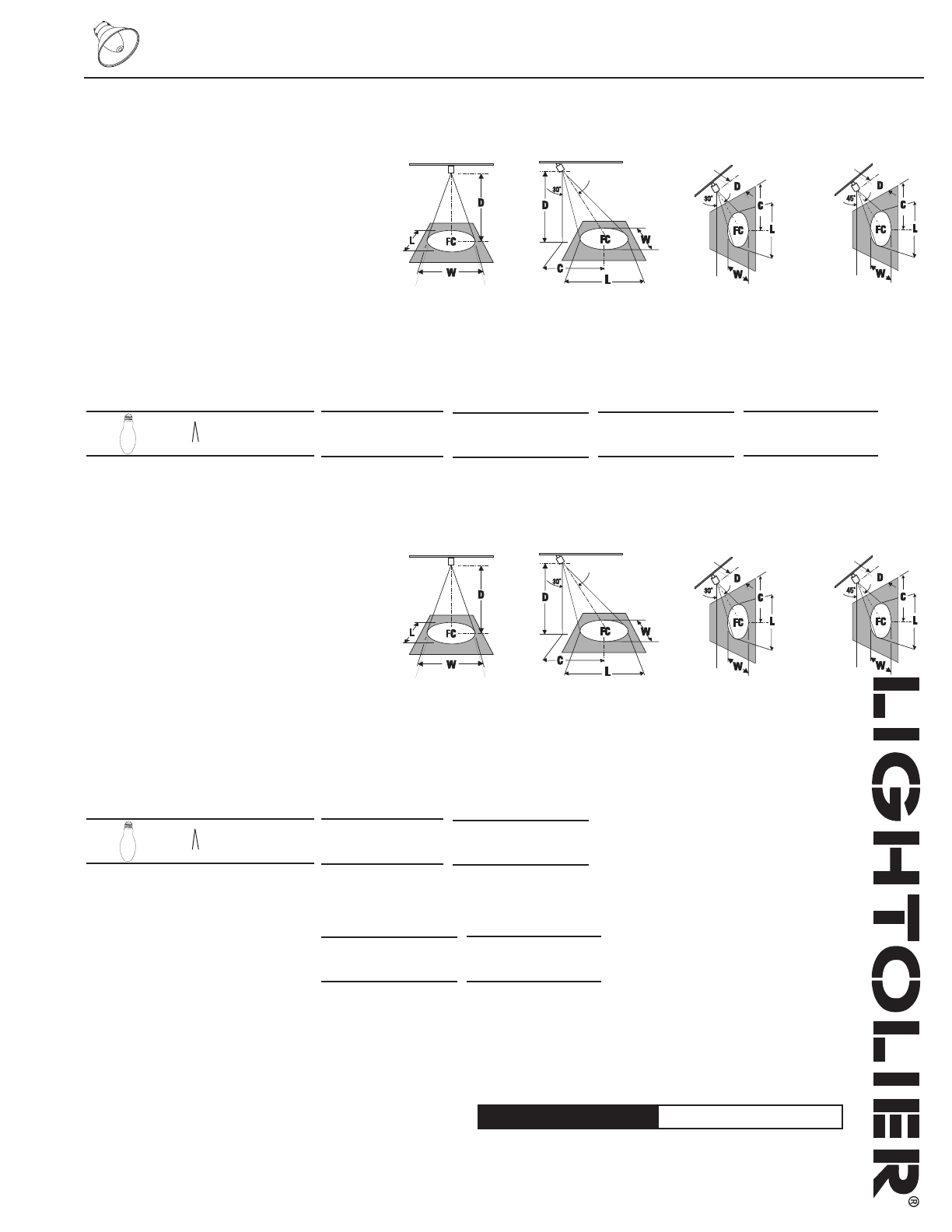
AIMING ANGLE: 0° Horizontal Aiming 30° Horizontal Aiming
DFC L W
DC FC L W
DC FC L W DC FC L W
Beam Spread
CBCP
Rated
(To 50% CBCP) Life (Hrs.)
12’ 492 1.7’ 1.7’
16’ 277 2.2’ 2.2’
20’ 177 2.8’ 2.8’
24’ 123 3.4’ 3.4’
10’ 5.8’ 460 1.9’ 1.6’
12’ 6.9’ 320 2.2’ 1.9’
20’ 11.5’ 115 3.7’ 3.2’
25’ 14.4’ 74 4.7’ 4.0’
5’ 8.7’ 354 2.8’ 1.4’
6’ 10.4’ 246 3.4’ 1.7’
10’ 17.3’ 89 5.7’ 2.8’
12’ 20.8’ 62 6.8’ 3.4’
8’ 8’ 392 2.2’ 1.6’
10’ 10’ 251 2.8’ 2.0’
16’ 16’ 98 4.5’ 3.2’
20’ 20’ 63 5.6’ 4.0’
70,888 10,000
8˚ X 8˚
For 50W: Multiply values by .68
Rated Lamp Life 10,000
For 100W: Multiply values by 1.5
Rated Lamp Life 12,500
AIMING ANGLE: 0° 30° Horizontal 30° Vertical 45° Vertical
L Beam Length D Distance
W Beam Width A Aiming Angle
C Distance to center beam FC Footcandles
L and W are the outer points where the candle power drops
to 50% of the maximum. FC are the initial footcandles at the
center of the beam.
Lamp data shown is typical. Consult lamp manufacturers for
availability and performance.
30° Vertical Aiming 45° Vertical Aiming