


Instruction Sheet Number 1104FESR
Page 1 of 2 Installation Procedure for Convertible IC/Non IC
Lightolier a Genlyte company www.lightolier.com
631 Airport Road, Fall River, MA 02720 • (508) 679-8131 • Fax (508) 674-4710
We reserve the right to change details of design, materials and finish.
© 2005 Genlyte Group LLC • B1005
Read and understand these instructions before installing fixture.
This fixture is intended for installation in accordance with the National Electrical Code and local regulations. To assure full compliance with local codes and
regulations, check with your local electrical inspector before installation. To prevent electrical shock, turn off electricity at fuse box before proceeding.
Retain these instructions for maintenance reference.
Warranty information on back – please retain.
Installation Procedure for Convertible IC/Non IC
Frame-In-Kits 1104F13ES/18ES/26ES and 1004F13ES/18ES/26ES
1104 Series FIK Use 1100 Series Trims (Finishing Sections) Only
1004 Series FIK Use 1000 Series Trims (Finishing Sections) Only
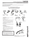
1. Cut Opening (Fig. A)
Use aperture sticker provided as a template to cut a hole in the ceiling. Cut
to outside edge of appropriate sticker line.
2. Wire-In (Fig. B)
Open hinged KNOCKOUT to allow NON-METALLIC CABLE to enter JUNCTION
BOX. Push CABLE through CLAMP.
Note: Wiring and connections must not be placed in JUNCTION BOX in a
manner which will interfere with the CLAMPS action to provide strain relief.
Wire to supply leads. WHITE FIXTURE LEAD to NEUTRAL SUPPLY LEAD.
BLACK FIXTURE LEAD to HOT (120V) SUPPLY LEAD. BARE FIXTURE WIRE to
SUPPLY GROUND. Use wirenuts (local hardware item). Place all electrical
connections in the J-BOX and close the J-BOX COVER.
3. Position J-Box (Fig. C)
Push J-BOX into cutout so that the two FEET are positioned over the edge of
the ceiling thickness. Bend J-BOX MOUNTING STRAP over into room side to
temporarily secure it.
4. Install Housing (Fig. D)
Push HOUSING straight up into ceiling.
Push bottom of RETAINING CLIPS out with thumb.
Push RETAINING CLIPS (3) down until HOUSING FLANGE is tight against
ceiling and insert RETAINING CLIP HOOKS into nearest SQUARE HOLES in
HOUSING.
Note: To remove housing, push RETAINING CLIPS down while unhooking
from SQUARE HOLES and then release CLIPS to the top of the slot. When
RETAINING CLIPS are at the top of the slot, retract the bottom of the
RETAINING CLIPS until they snap in place.
SECURE J-BOX:
Bend J-BOX MOUNTING STRAP into housing and secure.
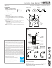
5. Airseal
®
Installation (optional)
Option 1: Install LAS56 Flange Gasket Kit (available separately).
Option 2: Install a bead of silicone caulking compound between the ceiling
opening and edge of HOUSING. Housings are tested in accordance with
ASTM E 283 (max 2 cfm @ 75 pa) and comply with WSEC & MEC when
installed as instructed. NOTE: If factory installed tape or knockouts are
removed from vertical adjustment slots in housing wall LAS56 Flange Gasket
Kit must be used (available separately).
Existing Construction
Fig. A
Cut Opening
Fig. B
Wire-In
Fig. C
Position J-Box
Fig. D
Install Housing &
Secure J-Box
Fig. E
Snap-On
Fig. F
Push-Up
J-BOX MOUNTING STRAP
FEET
J-BOX
BALLAST
JUNCTION BOX
NON-METALLIC
SHEATHED CABLE
12 OR 14 GAUGE
CABLE
CLAMP