


READ AND UNDERSTAND THESE INSTRUCTIONS BEFORE INSTALLING FIXTURE
This fixture is intended for installation in accordance with the National Electrical Code and local regulations.
To assure full compliance with local codes and regulations, check with your local electrical inspector before
installation. To prevent electrical shock, turn off electricity at fuse box before proceeding.
Retain these instructions for maintenance reference.
LIGHTOLIER a GENLYTE company.
631 Airport Road, Fall River, MA 02720
INSTRUCTION SHEET NO.
IS:1104ICN
C1204 Page 2 of 2
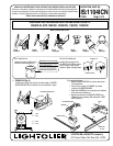
2. WIRE-IN (Fig. B)
Open hinged J-BOX COVER fully to its locked position (lift slightly to
unlock).
Open hinged KNOCK OUT to allow NON-METALLIC CABLE
to enter JUNCTION BOX. Push CABLE through CLAMP.
Note: Wiring and connections must not be placed in JUNCTION BOX
in a manner which will interfere with the CLAMPS action to
provide strain relief.
Wire to SUPPLY LEADS. WHITE FIXTURE LEAD to NEUTRAL SUPPLY
LEAD. BLACK FIXTURE LEAD to HOT (120V) SUPPLY LEAD. BARE FIX-
TURE WIRE to SUPPLY GROUND. Use wirenuts (local hardware item).
Place all electrical connections in the J-BOX and close the J-BOX
COVER.
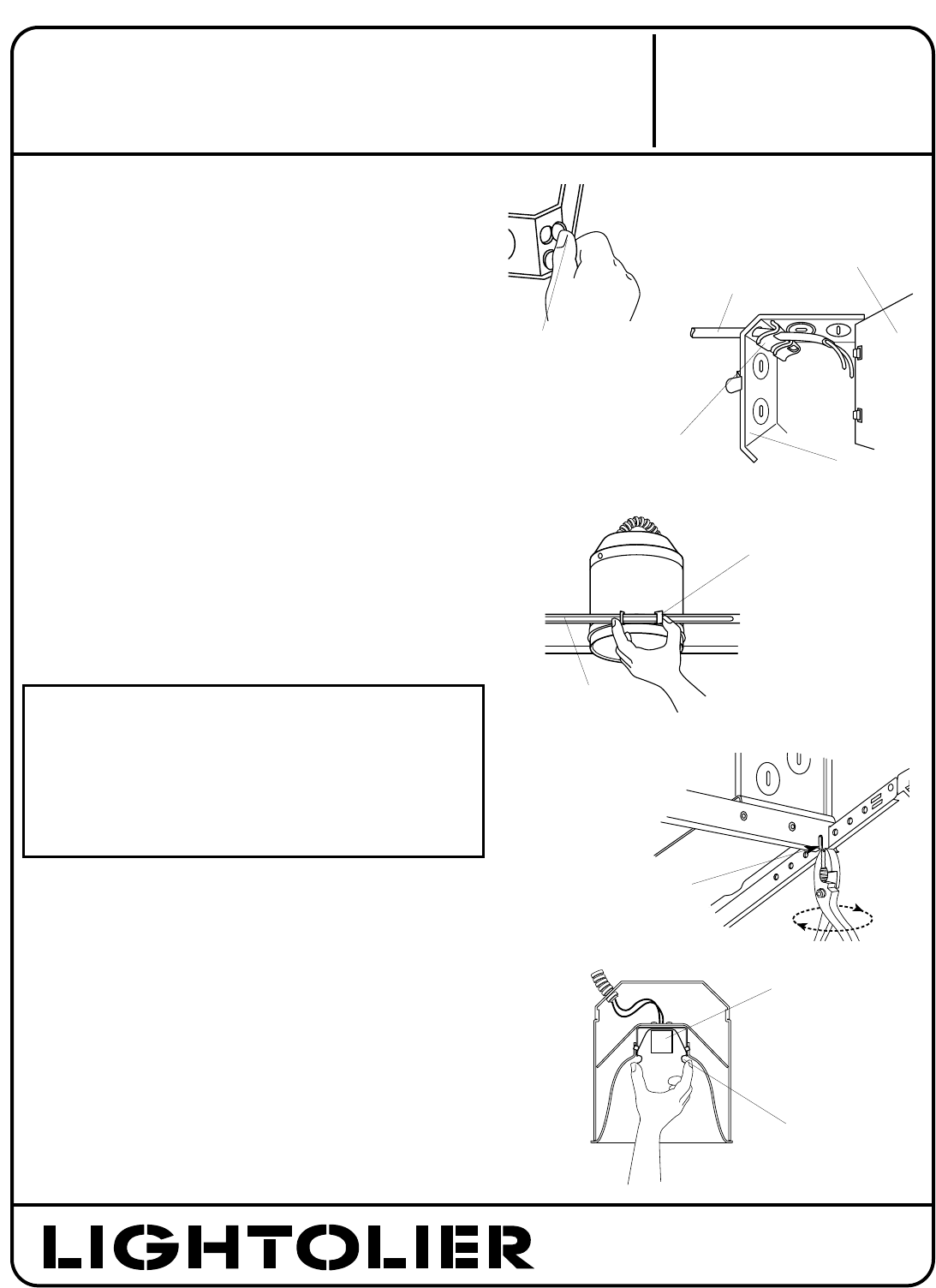
3. SWING-UP (Fig. C)
Extend MOUNTING BAR to reach opposite joist and fasten in place.
Adjust to desired position along MOUNTING BAR and lock in place.
4. CLOSE-IN (Fig. D)
Install plasterboard or other dry type ceiling. Hole in board
can be cut either on the floor or after the board is secured to the
ceiling using HOUSING opening as cutting guide. HOUSING is
secured by 3 screws which allow adjustment for variable ceiling
thicknesses.
5. AIRSEAL
®
INSTALLATION (optional)
Option 1: Install LAS56 Flange Gasket Kit (available separately).
Option 2: Install a bead of silicone caulking compound between
the ceiling opening and edge of HOUSING. Housings are tested
in accordance with ASTM E 283 (max 2 cfm @ 75 pa) and comply
with WSEC & MEC when installed as instructed.
NOTE: If factory installed tape or knockouts are removed from
vertical adjustment slots in housing wall install LAS56 Flange
Gasket Kit (available separately).
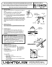
6. SNAP-ON (Fig. E)
Important - Insert SOCKET CUP in neck
of REFLECTOR making sure SPRING TABS
fully engage into SLOTS in REFLECTOR.
7. PUSH-UP (Fig. F)
Push REFLECTOR TRIM straight up until
it is tight against ceiling.
To remove TRIM:
• Turn off power to fixture
• Remove lamp
• Squeeze REFLECTOR SPRING from inside until the
TRIM disengages.
• To retrieve SOCKET CUP, pull on one of the SOCKET SPRING
LEGS to disengage.
SEE SEPARATE
REFLECTOR TRIM
INSTRUCTION
SHEETS
U.S. AND FOREIGN PATENTS PENDING
}
SQUEEZE CLIP
Squeeze to adjust,
release to lock
MOUNTING BAR
DEFORM MATERIAL HERE
FOR ADDITIONAL LOCK
HINGED KNOCK OUT
J-BOX COVER
NON-METALLIC
SHEATHED CABLE
(12 OR 14 GAUGE ONLY)
CABLE CLAMP
JUNCTION BOX
SOCKET CUP
REFLECTOR SPRING
®