


INSTRUCTION SHEET NO.
IS:1004ICV
B1204 Page 1 of 4
INSTALLATION PROCEDURE FOR LOW VOLTAGE
INSULATED CEILING FRAME-IN-KIT 1004ICV, 1004ICVN
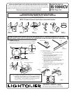
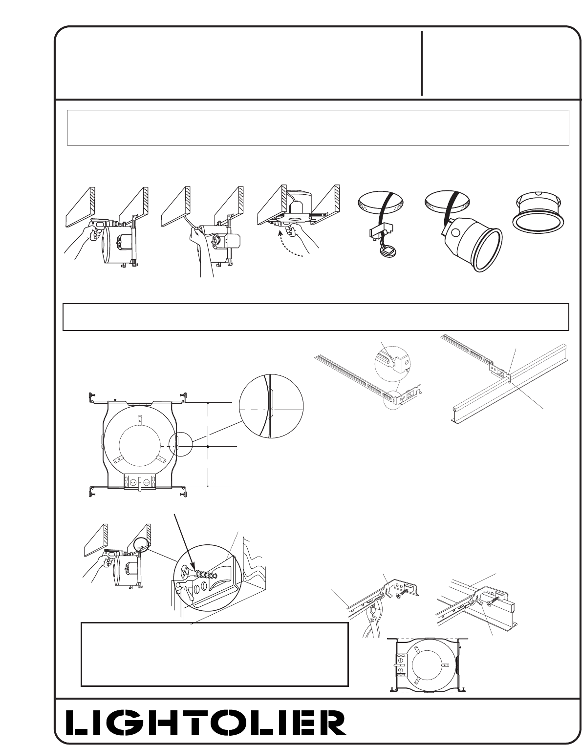
1. FRAME-IN (Fig. A)
Locate fixture along joist and line up bottom edge of HINGED
MOUNTING BAR with the bottom of joist and fasten in place.
Fig. A
Frame-In
Fig. B
Wire-In
Fig. C
Swing-Up
Fig. D
Close-In
Fig. E
Snap-On
Fig. F
Push-Up
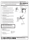
For suspended ceilings:
• Rotate HINGED BAR ENDS to position shown
and fully extend bars.
• Crimp bottom of edge of CHANNEL to prevent
rotation of HINGED BAR ENDS.
• Bend NON-HINGED end of mounting bar at
featured hole location and extend out.
• Position notched area of MOUNTING BARS onto
T-BAR and lock by bending TAB underneath
T-BAR BEAD as shown.
• For suspended ceiling, make certain that bottom
of Mounting Frame is no higher than 1” above
ceiling line.
READ AND UNDERSTAND THESE INSTRUCTIONS BEFORE INSTALLING FIXTURE
This fixture is intended for installation in accordance with the National Electrical Code and local regulations.
To assure full compliance with local codes and regulations, check with your local electrical inspector before
installation. To prevent electrical shock, turn off electricity at fuse box before proceeding.
Retain these instructions for maintenance reference.
®
LIGHTOLIER a GENLYTE company.
631 Airport Road, Fall River, MA 02720
NEW CONSTRUCTION
NOTE: I.C. Frame-in Kit may be used in direct contact with insulation.
WARNING: USE ONLY WITH LIGHTOLIER REFLECTOR TRIMS MARKED WITH I.C. LAMPING INFORMATION. USE OF OTHER
MANUFACTURERS’ TRIMS VOIDS THE UNDERWRITERS LABORATORIES LISTING AND COULD CONSTITUTE A FIRE HAZARD
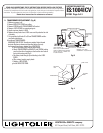
HINGED MOUNTING BAR
5
5
/
8”
6”
CENTER LINE OF
APERTURE OPENING
Fig. G
Note: Integral nail version available
TAB
T-BAR
HINGED BAR ENDS
CHANNEL
TAB
BEND AT TAB
BEND AT HOLE
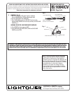
FOR JOIST SPACING LESS THAN 16” ON CENTER (TO 12” ON CENTER):
• MOUNTING BAR CHANNELS can be shortened and used as
nailing legs in tight spaces. Simply remove INNER BAR from
holed CHANNEL, bend CHANNEL at appropriate point and
use extra screw to secure it to the joist. (Fig. G)