


1
.—
(
INSTRUCTION SHEET NO.
INSTALLATION PROCEDURE FOR CALCULITE@
REMODELER Kl~
IS:A400RM
0890 Page 1 M 2
READ AND UNDER=AND THESE INSTRUCTIONS BEFORE INSTALLING FIXTURE.
This fixture is intended for installation in accordance with the National Electrical Code and local regulations.
To assure full compliance with local codes and regulations, check with your local electrical inspector before
ii%tallation. To prevent electrical shock, turn off electricity at fuse box before proceeding.
Retain these instructions for maintenance reference
WARNING—(RISK OF FIRE) DO NOTINWALLINSULATIONWITHIN 3 INCHESOF FIXTURE SIDES OR
WIRING COMPARTMENT, NOR ABOVE FIXTURE IN SUCH A MANNER TO ENTRAP HEAT.
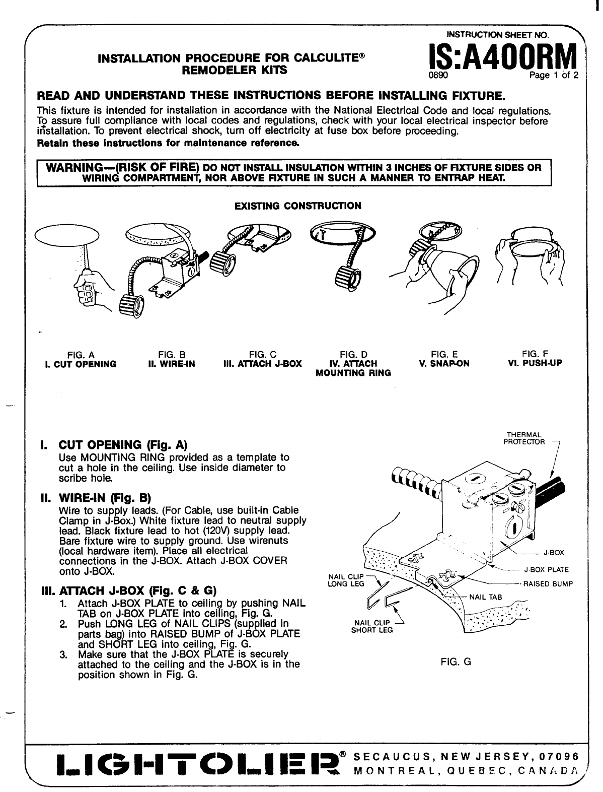
EXISllNG CONSTRUCllON
%pp
“...,.,. .,, t. ‘
,, ‘
e
Ca
8
10
e
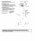
FIG. A
FIG. B FIG. C
L CUT OPENING
Il. WIRE-IN
Ill. ATTACH J-BOX
L
II.
CUT OPENING (Fig. A)
Use MOUNTING RING provided as a template to
cut a hole in the ceiling. Use inside diameter to
SCribe hole.
WIRE-IN (Fig. B)
Wire to suppl~leads. (For Cable, use built-in Cable
Clamp in J-Box.) White fixture lead to neutral supply
lead. Black fixture lead to hot (120V) supply lead.
Bare fixture wire to supply ground. Use wirenuts
(local hardware item). Place all electrical
connections in the J-BOX. Attach J-BOX COVER
onto J-BOX.
Ill.
AITACH J-BOX (Fig. C & G)
1. Attach J-BOX PLATE to ceiling by pushing NAIL
TAB on J-BOX PiATE into ceiling, Fig. G.
2. Push LONG LEG of NAIL CLIPS (supplied in
parts bag) into RAISED BUMP of J-BOX PIATE
and SHORT LEG into ceiling, Fig. G.
3. Make sure that the J-BOX PLATE is securely
attached to the ceiling and the J-BOX is in the
position shown in Fig. G.
FIG. D
IV. AITACH
MOUNTING RING
FIG. E
FIG. F
V. SNAPON
VI. PUSH-UP
THERMAL
PROTECTOR
7
~ J.BOX PLATE
LONG LEG
- RAISED BUMP
FiG. G