


-30-
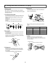
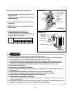
3. Connecting The Cable Between Indoor Unit and Outdoor Unit
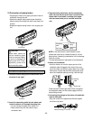
1) Connect the cable to the Indoor unit.
• Connect the cable to the indoor unit by connecting the wires to the terminals on the control board in
dividually according to the outdoor unit connection. (Ensure that the color of the wires of the outdoor unit and
the terminal No. are the same as those of the indoor unit.)
The earth wire should be longer than the common wires.
Air
Conditioner
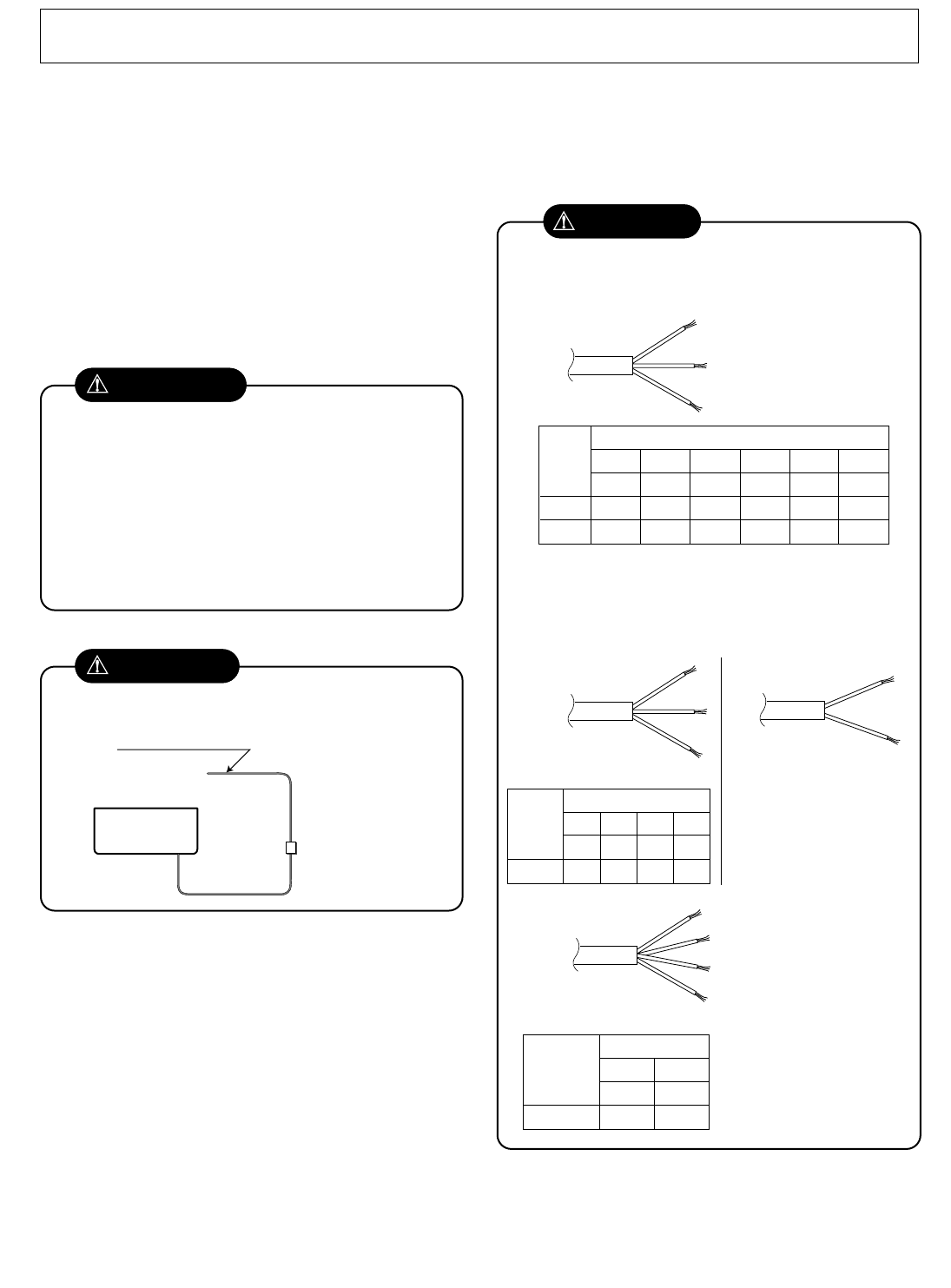
Main power source
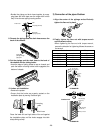
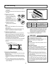
If a power plug is not to be used, provide a circuit breaker
between power source and the unit as shown below.
Circuit Breaker
Use a circuit
breaker or time
delay fuse.
CAUTION
CAUTION
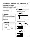
The power cord connected to the "A" unit should be
complied with the following specifications
(Type "B" approved by HAR or SAA).
Grade
5k~9K 12k~14k 18k 24k~28k 30k, 32k 36k, 38k
0.75 1.0 1.5 2.5 2.5 5.5
Unit(A) Indoor Indoor Indoor Indoor Outdoor Outdoor
Cable Type(B)
H05VV-F H05VV-F H05VV-F H05VV-F H05RN-F H05RN-F
NORMAL
CROSS
-SECTIONAL
AREA
5k~9k 12k~14k 18k 24k~28k
0.75 1.0 1.5 2.5
Cable Type(B) H07RN-F H07RN-F H07RN-F H07RN-F
NORMAL
CROSS
-SECTIONAL
AREA
Grade
30k, 32k 36k, 38k
0.75 0.75
Cable Type(B) H07RN-F H07RN-F
NORMAL CROSS
-SECTIONAL AREA
Grade
(mm
2
)
(mm
2
)
(mm
2
)
The power connecting cable connected to the indoor
and outdoor unit should be complied with the following
specifications
(Type "B" approved by HAR or SAA).
NORMAL
CROSS-SECTIONAL
AREA 0.75mm
2
• The above circuit diagram is subject to change with-
out notice.
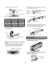
• Be sure to connect wires according to the wiring dia-
gram.
• Connect the wires firmly, so that not to be pulled out
easily.
• Connect the wires according to color codes by refer-
ring the wiring diagram.
CAUTION
• When installing, refer to the circuit diagram on the
Control Box of Indoor Unit.
• When installing, refer to the wiring diagram on the
Control Cover Inside Outdoor Unit.