


ELECTROSTATIC DISCHARGE (ESD) PRECAUTIONS
PROCEDURE
CAUTION: Electrostatic discharge can affect electronic
components. Take precautions during furnace installation
and servicing to protect the furnace electronic control.
Precautions will prevent electrostatic discharges from
personnel and hand tools which are held during the
procedure. These precautions will help to avoid exposing
the control to electrostatic discharge by putting the
furnace, the control, and the person at the same electro-
static potential.
1. Disconnect all power to the furnace. DO NOT TOUCH
THE CONTROL OR ANY WIRE CONNECTED TO THE
CONTROL PRIOR TO DISCHARGING YOUR BODY’S
ELECTROSTATIC CHARGE TO GROUND.
2. Firmly touch a clean, unpainted, metal surface of the
furnace chassis which is close to the control. Tools held in
a person’s hand during grounding will be satisfactorily
discharged.
3. After touching the chassis you may proceed to service the
control or connecting wires as long as you do nothing that
recharges your body with static electricity (for example; DO
NOT move or shuffle your feet, DO NOT touch un-
grounded objects, etc.).
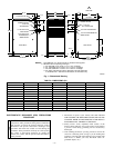
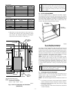
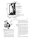
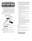
TABLE 2—DIMENSIONS (IN.)
UNIT SIZE A D E VENT CONN SHIP. WT (LB)
024045 14-3/16 12-9/16 12-11/16 4 122
036045 14-3/16 12-9/16 12-11/16 4 124
024070 14-3/16 12-9/16 12-11/16 4 132
036070 14-3/16 12-9/16 12-11/16 4 134
042091 17-1/2 15-7/8 16 4 150
048091 21 19-3/8 19-1/2 4 154
036110 17-1/2 15-7/8 16 4 160
048111 21 19-3/8 19-1/2 4 166
060111 24-1/2 22-7/8 23 4 184
048135 21 19-3/8 19-1/2 5 178
060135 24-1/2 22-7/8 23 5 194
060155 24-1/2 22-7/8 23 5 204
Fig. 1—Dimensional Drawing
A88367
A
D
13
⁄16″
E
11
⁄16″
11
⁄16″
28
1
⁄2″
39
7
⁄8″
24
5
⁄16″
11
⁄16″
3″
2
1
⁄16″
1″
12
5
⁄16″
5
3
⁄8″
5
13
⁄16″
2
3
⁄8″
AIR INLET
7
⁄8-IN. DIA HOLE
POWER ENTRY
7
⁄8-IN. DIA
ACCESSORY
1
3
⁄4-IN. DIA HOLE
GAS ENTRY
1
⁄2-IN. DIA HOLE
THERMOSTAT
WIRE ENTRY
SIDE INLET
FLUE COLLAR
1. Two additional
7
⁄8-in. dia knockouts are located in the top plate.
2. Minimum return-air opening at furnace:
a. For 800 CFM–16-in. round or 14
1
⁄2 x 12-in. rectangle.
b. For 1200 CFM–20-in. round or 14
1
⁄2 x 19
1
⁄2-in. rectangle.
c. For 1600 CFM–22-in. round or 14
1
⁄2 x 23
1
⁄4-in. rectangle.
d. For airflow requirements above 1800 CFM, use both side inlets,
a combination of 1 side inlet and the bottom, or the bottom only.
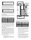
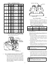
NOTES:
5
3
⁄8″
5
13
⁄16″
2
3
⁄8″
2
11
⁄16″
1″
2
1
⁄16″
19″
13
⁄16″
7
⁄8-IN. DIA
POWER ENTRY
AIRFLOW
OUTLET
1
1
⁄2-IN. DIA
R.H. GAS ENTRY
7
⁄8-IN. DIA ACCESSORY
1
⁄2-IN. DIA THERMOSTAT
WIRE ENTRY
SIDE INLET
14
1
⁄2″
1″
23
1
⁄4″
SIDE RETURN
DUCT LOCATION
1
3
⁄4″
TYP 1″
5
⁄8″
TYP
—2—