


13
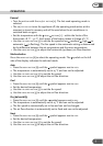
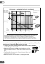
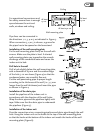
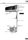
For operational convenience and
for safety, ensure there is enough
space between the unit and
walls, windows and ceiling.
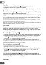
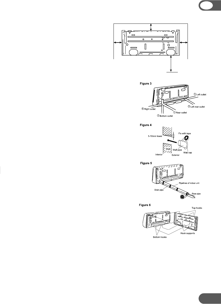
Pipe lines can be connected in
the directions 1, 2, 3, 4 or 5 as indicated in Figure 3.
When connection 3, 4 or 5 is chosen, a groove for
the pipes has to be opened on the base stand.
Installation of the wall-mounting plate
Fix the wall-mounting plate firmly on the wall with
screws. Make sure the plate is level. A slanted
wall-mounting plate may jeopardize the smooth
discharge of the condensed water and cause the
indoor unit to leak.
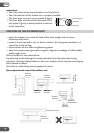
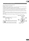
Drill hole in the wall
Drill a hole slightly below the wall-mounting plate,
with a diameter of 65 mm and the outdoor edge
of the hole 5–10 mm lower (Figure 4) so that the
condensed water can smoothly flow out.
Cut the wall penetrating pipe to proper length
according to the thickness of the wall (i.e. 3–5 mm
longer than the wall thickness) and insert the pipe
as shown in Figure 4.
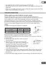
Installation of the drain pipe
Install the pipelines of the indoor unit in
accordance with the direction of the wall holes.
Wrap the drain pipe and the pipelines tightly with
tape. Make sure that the drain pipe is underneath
the pipelines (Figure 5).
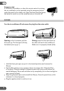
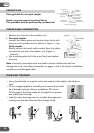
Installation of the indoor unit
Pass the connection wires, connecting pipelines and drain pipe through the wall
hole. Hang the indoor unit on the hooks at the top of the wall-mounting plate
so that the hooks at the bottom of the indoor unit match the hooks of the wall-
mounting plate (Figure 6).
GB
At least 10 cm
At least
15 cm
At least
15 cm
At least 230 cm
Floor
Wall-mounting plate
Ceiling