PLANNING YOUR INSTALLATION– Model CI2000HT
PAGE 9
MODEL CI2000HT
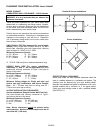
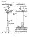
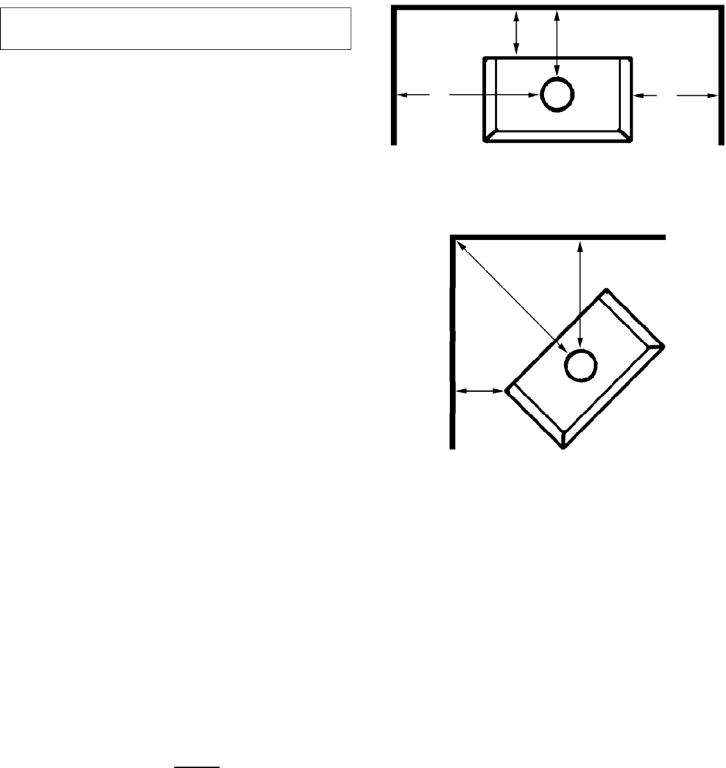
COMBUSTIBLE WALL CLEARANCE – USA & Canada
WARNING: It is very important that you observe the
minimum clearances.
There are listed clearances for your stove which were
determined in a Laboratory test using various "classes"
of stove pipe or chimney. Minimums are first established
for the stove itself and increased based on how much
heat is transferred by each class of pipe.
Position the unit no closer than the minimum clearances
to combustible materials. Check that no overhead cross
members in the ceiling or roof will be cut. Reposition
unit if necessary being careful not to move closer than
the minimum clearances.
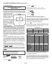
SINGLE WALL PIPE (Not approved for alcove instal-
lations) Using single wall 24 MSG black or 25 MSG
blued steel connector pipe with factory-built chimney
listed to either UL 103HT or ULC S629.
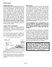
Minimum Clearances (inches)
A. 18" / 457mm D. 13" / 330mm
B. 32" / 813mm E. 20" / 508mm
C. 27" / 686mm F. 16" / 406mm
G. 35 3/16” / 894 mm (this is a reference dimension only)
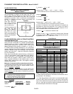
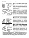
DOUBLE WALL PIPE (For alcove installations,
clearances "C" and "F" are not applicable) Use listed
double wall chimney connector or Type L vent pipe to
the top of the stove.
Minimum Clearances (Inches)
A. 14 1/2" / 368mm D. 10" / 254mm
B. 28 1/2" / 724mm E. 17" / 432mm
C. 18" / 457mm F. 7" / 178mm
Minimum Ceiling Height for Single wall pipe and
double wall pipe installations and Alcove Installa-
tions – 60" / 1524mm from floor to ceiling and 29" /
737mm from stove top to ceiling.
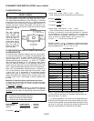
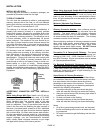
ALCOVE INSTALLATION CLEARANCES
Alcove Installations Require Double Wall Pipe Only
Use listed double wall chimney connector or Type L
vent pipe to the top of the stove.
Minimum Clearances (Inches)
A. 14 1/2" (368 mm) D. 10" (254 mm)
B. 28 1/2" (724 mm) E. 17" (432 mm)
C. N/A F. N/A
Note: Alcove clearances cannot
be reduced using
wall protection. Maximum alcove depth must be no
more than 48" (1220 mm).
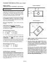
Parallel & Alcove Installations
Corner Installation
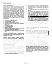
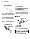
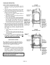
PROTECTED WALL CLEARANCE
Some local codes will allow reduced clearances when the
stove is installed adjacent to a protected wall system. The
variance must be approved by your local building official.
Normally, the protected wall system is defined as a non- com-
bustible material with a minimum of 1" air space behind.
Check your local building codes or with a qualified installer
(Ref. NFPA 211).
A
D
B E
F
C
G


