Page 22
506637−01 11/10
6. Set the thermostat for a cooling demand. Turn on
power to the indoor indoor unit and close the outdoor
unit disconnect switch to start the unit.
7. Recheck voltage while the unit is running. Power must
be within range shown on the nameplate.
8. Check system for sufficient refrigerant by using the
procedures listed under System Charge.
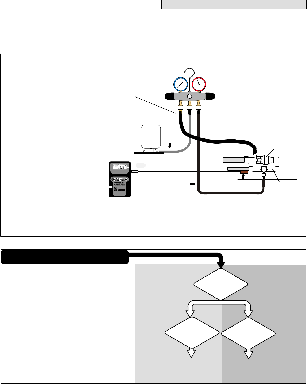
System Refrigerant
This section outlines procedures for:
1. Connecting gauge set for testing and charging;
2. Checking and adjusting indoor airflow;
3. Adding or removing refrigerant.
TO LIQUID
LINE SERVICE
VALVE
TEMPERATURE
SENSOR
DIGITAL SCALE
REFRIGERANT TANK
TEMPERATURE SENSOR
(LIQUID LINE)
MANIFOLD GAUGE SET
AClose manifold gauge set valves and connect the center hose to a cylinder of HFC−410A. Set for liquid phase charging.
BConnect the manifold gauge set’s low pressure side to the suction line service port.
CConnect the manifold gauge set’s high pressure side to the liquid line service port.
DPosition temperature sensor on liquid line near liquid line service port.
OUTDOOR UNIT
CHARGE IN
LIQUID PHASE
CONNECTIONS FOR TESTING AND CHARGING
GAUGE SET
A
C
D
LOW
HIGH
B
SUCTION LINE
SERVICE PORT
CONNECTION
VAPOR LINE
SERVICE VALVE
LIQUID LINE
SERVICE VALVE
Figure 15. Gauge Set Setup and Connections
WHEN TO CHARGE?
S Warm weather best
S Can charge in colder weather
CHARGE METHOD? Determine by:
S Metering device type
S Outdoor ambient temperature
REQUIREMENTS:
S Sufficient heat load in structure
S Indoor temperature between 70-80ºF (21−26ºC)
S Manifold gauge set connected to unit
S Thermometers:
− to measure outdoor ambient temperature
− to measure liquid line temperature
− to measure suction line temperature
APPROACH OR
SUBCOOLING
WEIGH-IN
64ºF (17.7ºC)
and BELOW
65ºF (18.3ºC)
and ABOVE
START: Determine how refrigerant is metered
TXV
OUTDOOR AMBIENT
TEMPERATURE
(SECOND STAGE − HIGH
CAPACITY)
Figure 16. Determining Charge Method


