


Page 11
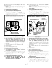
G-Horizontal Venting Concentric Kit - Residential
1-For horizontal residential installations the 45/60/75
units are certified as Category I appliances with a
concentric vent/adapter/cap kit. The only concentric
vent/adapter/cap kits that may be used are the kits
supplied by Advanced Distributor Products. The vent
used to connect from the concentric adapter to the
unit may be single wall material minimum 25 GSG
(0.46mm) galvanized steel or equivalent grade
stainless steel installed according to the sections
Venting A - General Recommendations and
Requirements and C - Horizontal Venting General
and G - Horizontal Venting Concentric Kit -
Residential. Refer to figure 7. The air inlet may be
single wall material or U.L. listed single wall flex vent
connector.
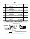
2-The vent pipe diameter for horizontal residential
installations shall be 4” (100mm) on 45/60/75 units.
Refer to table 4.
3-The maximum vent length is 5’ (1.5m) plus one 90-
degree elbow.
4-The vent must maintain a ¼” rise per foot of slope
upwards toward the termination.
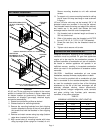
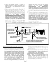
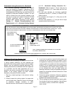
FIGURE 7
HORIZONTAL VENTING – CONCENTRIC VENT INSTALLATION
LISTED THIMBLE
THROUGH
COMBUSTIBLE WALL
GROUND LEVEL
NOTE - MINIMUM HORIZONTAL LENGTH 3 FT. (91.4 CM) NOT
INCLUDING TERMINATION.
VENT AND AIR INLET CONNECTORS FROM UNIT TO CONCENTRIC ADAPTER MAY BE SINGLE WALL (26 GSG) GALV. OR
EQUIVALENT STAINLESS STEEL SEALED ACCORDING TO THESE INSTALLATION INSTRUCTIONS. SLOPE VENT + 1/4 INCH
FOR 1 FOOT RUN MINIMUM. AIR INLET MAY ALSO BE U.L. LISTED SINGLE WALL FLEX VENT CONNECTOR.
COMMON VENTING NOT ALLOWED WHEN HORIZONTALLY VENTING THE UNIT HEATER.
VENT TERMINATION
AND AIR INLET
TERMINATION
12” (30.5 CM) MINIMUM ABOVE
HIGHEST SNOWFALL
H-Removal Of Unit From Common Vent
In the event that an existing unit heater is removed from
a venting system commonly run with separate gas
appliances, the venting system is likely to be too large to
properly vent the remaining attached appliances. The
following test should be conducted while each appliance
is in operation and the other appliances are not in
operation, yet remain connected to the common venting
system. If the venting system has been installed
improperly, the system must be corrected.
1- Seal any unused openings in the common venting
system.
2- Visually inspect the venting system for proper size
and horizontal pitch. Determine there is no blockage
or restriction, leakage, corrosion, or other
deficiencies which could cause an unsafe condition.
3- In so far as is practical, close all building doors and
windows and all doors between the space in which
the appliances remaining connected to the common
venting system are located and other spaces of the
building. Turn on clothes dryers and any appliances
not connected to the common venting system. Turn
on any exhaust fans, such as range hoods and
bathroom exhausts, so they will operate at maximum
speed. Do not operate a summer exhaust fan. Close
fireplace dampers.
4- Follow the lighting instructions. Place the appliance
being inspected in operation. Adjust thermostat so
appliance will operate continuously.
5- Test for spillage at the draft hood relief opening after
five minutes of main burner operation. Use the flame
of a match or candle, or smoke from a cigarette,
cigar, or pipe.