


Page 12
6- After it has been determined that each appliance
remaining connected to the common venting system
properly vents when tested as outlined above, return
doors, windows, exhaust fans, fireplace dampers
and any other gas-burning appliance to their
previous condition of use.
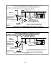
7- If improper venting is observed during any of the
above tests, the common venting system must be
corrected. The common venting system should be
resized to approach the minimum size as
determined by using the appropriate tables in
Appendix G in the current standards of the National
Fuel Gas Code, ANSI Z223-1 in the U.S.A. and the
appropriate Category I Natural Gas and Propane
appliances venting sizing tables in the current
standards of the CSA-B149.1 and .2 in the Natural
Gas and Propane Installation Code in Canada.
NOTE - Local codes may supersede any of the above
provisions.
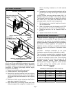
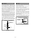
Electrical Connections
NOTE - These unit heaters use a direct spark ignition
system. There is no pilot necessary as the spark lights
the main burner as the gas valve is turned on. The direct
spark ignition control board emits radio noise as the
sparking process is underway. The level of energy may
be sufficient to disturb a logic circuit in a microprocessor
controlled thermostat. It is recommended that an
isolation relay be used when connecting the unit heaters
to a microprocessor controlled thermostat. Install the
thermostat according to instructions provided. Select
circuit protection and wire size according to the unit
rating plate. Install a separate disconnect switch
(protected by either fuse or circuit breaker) near the unit
so that power can be turned off for servicing. Connect
wiring through knockout on the junction box located on
the side of the unit heater. Refer to heater wiring
diagram for connection information. Use 18 gauge wire
or larger for thermostat connections.
Electrically ground unit in accordance with local codes
or, in the absence of local codes, in accordance with the
current National Electrical Code (ANSI/NFPA No. 70) in
the U.S.A., and in Canada with the current Canadian
Electrical Code, Part 1 (CSA C22.1).
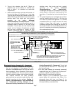
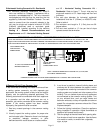
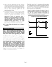
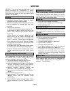
Make line voltage connections as shown in figure 8.
Connect field wiring as shown on wiring diagram on
unit. Also refer to typical diagram in this manual. An
additional thermostat wire must be run to terminal “G"
on heater when continuous blower is desired.
FIGURE 8
LINE VOLTAGE FIELD WIRING
L1
WHITE
N
BLACK
UNIT ELECTRICAL BOX