


Page 4
.
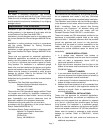
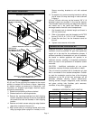
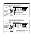
Unit Heater Installation
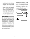
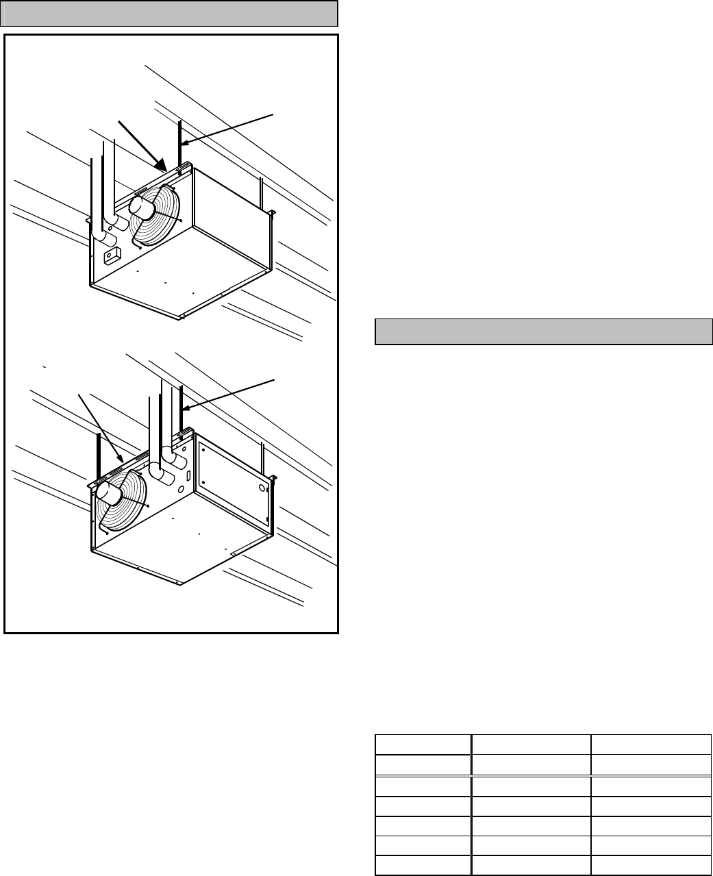
45, 60, and 75 size units may be installed in the normal
position or inverted 180° as shown in figure 1 depending
on desired location as governed by clearances, vent
connection, air direction, gas supply, electrical supply
and service accessibility.
1- Rotate louvers directing airflow as desired.
2- Choose location for mounting brackets.
3- Remove the mounting brackets from their shipping
location (attached to the top of the unit) and replace
the screws that held the brackets in their shipping
location.
4- Remove and retain screws along top edge (bottom
edge when inverted) of front of unit.
5- Align screw holes on mounting bracket with holes
along top edge (either upright or inverted) of unit.
Secure mounting brackets to unit with retained
screws.
6- To support unit, secure mounting bracket to ceiling
joist or truss. Unit may also hang on rods as shown
in figure 1.
100 and 125 size units may not be inverted, 3/8” X 16
threaded inserts are provided in the top the cabinet.
Two threaded inserts are along one edge of the cabinet,
two inserts are in the panel that divides the heat
exchanger section from the control compartment.
1- Cut threaded rods to desired length and thread a
3/8” nut onto the rod.
2- Slide a flat washer onto the threaded rod AFTER
the nut (7/16” I.D. X 1” O.D. X 1/16” THK washer).
3- Screw the rods (four) into the threaded inserts on
the unit.
4- Tighten nuts to secure unit to rods.
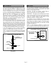
Combustion and Ventilation Air
Adequate facilities for supplying air for combustion and
ventilation must be provided. All gas fired appliances
require air to be used for the combustion process. If
sufficient quantities of combustion air are not available,
the heater or another appliance will operate in an
inefficient manner, resulting in incomplete combustion
which can result in the production of excessive carbon
monoxide.
CAUTION - Insufficient combustion air can cause
headaches, nausea, dizziness, asphyxiation or death.
This unit must be provided with a combustion air pipe
that is connected to the outside atmosphere. Outdoor
air used for combustion must be free of the following
substances or the life of the heat exchanger will be
adversely affected: chlorine, carbon tetrachloride,
cleaning solvent, halogen refrigerants, acids, cements
and glues, printing inks, fluorides, paint removers,
varnishes, or any other corrosives.
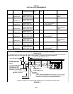
TABLE 2
MAXIMUM HORIZONTAL VENT LENGTHS
Model 45, 60, 75 100, 125
No. of Elbows Ft (M) Ft (M)
1 25 (7.6) 25 (7.6)
2 20 (6.1) 20 (6.1)
3 15 (4.6) 15 (4.6)
4 10 (3.0) 10 (3.0)
5 5 (1.5) 5 (1.5)
FIGURE 1
INSTALL UNIT HEATER
OPTIONAL INVERTED POSITION (ABOVE)
45, 60, AND 75 MODELS ONLY
SUPPORT
RODS
MOUNTING BRACKETS
(45, 60, & 75 MODELS
ONLY)
NORMAL POSITION (ABOVE) ALL MODELS
SUPPORT
RODS
MOUNTING
BRACKETS (45, 60,
&75 MODELS ONLY)