


Beforestartingunit,makesuretheoiltankisadequately
filledwithcleanNo,1orNo,2furnaceoil,
NOTE - Water, rust or other contaminants in oil supply sys-
tem will cause malfunction and failure of the internal parts
of the fuel pump.
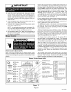
CAUTION
1, Set thermostat for heating demand and turn on electri-
cal supply to unit,
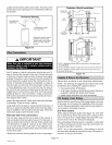
2, Check initial air adjustment, All units are equipped with
an air adjustment dial on the right side of the burner,
See burner parts arrangement illustration.
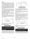
3, Turn unit on. Place a can or container under the bleed
port located on the fuel pump. Loosen nut on bleed
port to release air and oil mixture from fuel line. Allow
mixture to escape until a steady stream of oil is emitted
from the port. Drain at least 1/2 pint of oil from the
pump, Retighten the nut on bleed port. If lockout oc-
curs, press reset button and continue with bleed pro-
cedure,
NOTE - A two-pipe fuel system will normally bleed it-
self by forcing air back to the tank through the return
line. This type of bleeding procedure is not necessary.
4, If burner fails to start, push reset button on primary
safety control and the burner motor reset button. See
part arrangement illustration,
CAUTION
5, If the burner fails to light again, refer to the trouble-
shooting section in this manual,
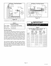
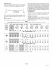
Measuring Fuel Pump Pressure
Measure fuel pump pressure with unit off. Attach pressure
gauge to pump outlet, Turn unit on and check pressure and
compare to table 7. Adjust if necessary,
Measuring Temperature Rise
To measure temperature rise, place plenum thermometers
in warm air and return air plenums, Locate thermometer in
warm air plenum where thermometer will not "see" the heat
exchanger to prevent it from picking up radiant heat. Set
thermostat to its highest setting to start unit, After plenum
thermometers have reached their highest and steadiest
readings, subtract the readings, The difference in temper-
atures in the supply and return air plenums should approxi-
mate the temperature rise range listed in table 7 and the
appliance rating plate, If the rise is above the range shown
in the table, check for high static pressure.
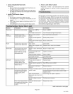
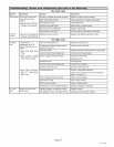
Table 7
Nozzle Size, Input Output Temp
O23V Spray Angle, Pump Rating Rating Rise
Unit & Pattern PSIG BTU/Hr BTU/Hr Head F°
-70 .50GPH-80 ° A 100 70,000 57,000 FB0 60-70
-90 .65GPH-80 ° B 100 90,000 72,000 FB0 60-70
-105 .65GPH-80 ° B 140 105,000 84,000 FB3 65-75
-120 .75GPH-80 ° B 140 119,000 105,000 FB3 70-80
-140 .85GPH-80 ° B 140 140,000 112,000 FB6 65-75
-154 1.0GPH-80 ° B 140 154,000 125,000 FB6 70-80
Adjusting Limit Control
DO NOT adjust limit control - it is preset at the factory,
Adjusting and Testing Burner
The following instructions are essential to the proper op-
eration of O23V series oil furnaces, To prevent sooting,
these instructions must be followed in sequence:
1, Draft--This test should be taken at the breach be-
tween the outlet of the vent connector and the baro-
metric draft control. Generally a 1/4" hole will need to
be drilled for the draft gauge to be inserted into the vent
connector.
A minimum of 0,03 draft must be established without
the burner in operation. With the burner in operation,
the draft should be 0,04 to 0.05. This is VERY critical to
the flame retention head burners.
Oil furnace installations also require careful inspection
to make sure the chimney is in good shape and can ac-
commodate the products of combustion, The temper-
ature in the unconditioned space will also affect the
draft if long vent connectors are allowed to get too
cold,
2. Overfire Draft--This test should be taken with the
burner in operation. Remove the screw from the center
of the inspection port, Insert your draft gauge into the
hole.
A reading of the overfire draft should be 0.02 less than
the reading found in the vent connector. If a positive
reading is seen at this point, the combustion fan is
pumping too much air into the heat exchanger. Make
the necessary adjustments at the air adjustment dial.
3, Smoke Test--The smoke test should be taken at the
hole drilled in step 1,
Using a smoke test gun adjust the air inlet shutter so
that you will have just a trace of smoke, Somewhere
between a 0 and #1 smoke, This is the starting point,
Do not stop here.
4, CO2 Test--Again, take this sample at the vent pipe,
With the unit firing at a trace of smoke, take a sample of
the CO2, From the results of this test, a "window of op-
eration" will be determined. This window of operation
establishes some tolerance, The tolerance the install-
er builds in provides room within the set-up for those
things which might affect combustion. Those things
which might affect combustion can then do so without
Page 17
O23V SERIES