


Neitherthenozzlesettingnortheairadjustmentsarefac-
toryset.Thefurnaceisfiretestedandthelimitcontrolis
checkedto makesureitfunctionsproperly;nofactoryset-
tingsaremade.Duringinstallation,thefurnacemustbe
"setup."Theinstallingdealer/contractormusthaveand
usepropertestequipmentinordertocorrectlysetupthe
oilfurnace.Propertestingequipmentisrequiredtoensure
correctoperationoftheunit.Theuseoftestequipmentis
nowmorecriticalthaneverduetotightertolerancesneed-
edto keepthefurnaceoperatingefficiently.
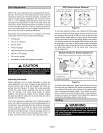
Amongthetestequipmentfor anoilfurnace,theproper
combustiontestkitshouldcontainthefollowing:
• Draftgauge
• CO 2 or 0 2 analyzer
• Smoke tester
• Pressure gauge
• High temperature thermometer
• Beckett T-500 gauge
• Oil vacuum gauge
• Knowledge of proper test equipment operation
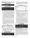
CAUTION
Adjusting the Nozzle
Proper adjustment d the nozzle assembly is critical be-
cause alignment may have changed during shipping. Be-
fore the furnace and oil lines are installed, the nozzle as-
sembly must be checked. To check the nozzle assembly,
remove the entire burner assembly (not just the nozzle)
from the furnace. The lower firing nozzle is factory
installed. This should be verified by the installer. Inspect
the spark transformer leads also to ensure they are still at-
tached to the electrodes.
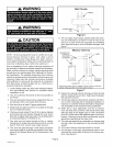
The burner assembly is attached to the vestibule panel by
three nuts. Slots are provided in the mounting flange for re-
moving the burner assembly from the vestibule. By loosen-
ing the nuts and by turning the whole burner assembly
counterclockwise (figure 4), the entire burner assembly
will come out of the furnace. There is adequate wire to re-
move the burner without disconnecting wires. Once re-
moved, turn the burner around in the vest panel area.
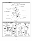
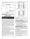
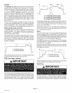
O23V Series Burner Removal
Loosen three nuts which at-
tach burner to vest panel.
Rotate burner counterclockwise on
slots then pull toward you,
Figure 4
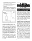
To correctly adjust the nozzle, use a Beckett #T-500 gauge
Insert the small end of the gauge into the end of the cone
and measure from the flat of the end cone to the tip of the
nozzle. When nozzle depth is correct, the tip of the nozzle
should just touch the end of the gauge. Refer to the illustra-
tion sheet provided with the gauge. Note that the scale side
of the gauge is not used for this purpose. Make corrections
by sliding the nozzle assembly forward or backward within
the blast tube (figure 5). At the same time, check the
nozzle alignment.
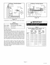
Beckett Oil Burner Nozzle Adjustment
Burner must be removed from furnace for this procedure.
GAUGE 2 1
TO ADJUST NOZZLE:
1-Loosen screw.
2-Slide entire nozzle/electrode assembly back and forth until nozzle
just touches the gauge.
Figure 5
To check nozzle alignment, again insert the small end into
the end cone and measure the nozzle and electrode align-
ment against the center lines marked on the gauge (again
refer to enclosed illustration sheet). If the nozzle is not cen-
tered, but found to be too far left or right, a new nozzle as-
sembly will need to be ordered. Do not attempt to adjust by
bending the 90 degree elbow in the oil line.
A WARNING
Page 5
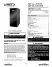
O23V SERIES