


causing the unit to start sooting/smoking, Things
which might affect combustion include a nozzle going
bad, draft that changes during different climatic condi-
tions, dirty oil, dirt obstructing the air inlet, etc.
To build in a "window of operation," set up the burner to
be 2% less in CO2, For example, if you find a reading of
12% CO2, adjust the air inlet shutter to increase the air
and drop the CO2 to 10%,
5. Retest the Smoke--With a drop in the CO2 and in-
crease in the air you should see that the smoke has re-
turned to 0,
6. Retest the Overfire Draft--This test serves to con-
firm that you have not increased the air too much,
Again you do not want a positive pressure at the test
port. Itshould still be 0.02 less than the draft pressure
reading taken at the breach. You may need to increase
the stack draft by adjusting the barometric draft con-
trol,
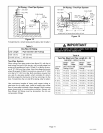
7. Stack Temperature--Take a stack temperature read-
ing in the vent pipe. Subtract the room air temperature
from the stack temperature. This will give you the net
stack temperature, Use the efficiency charts provided
in most CO2 analyzers to determine furnace efficiency.
4, Remove the locking screw and cap from the observa-
tion tube and with the spiral wire brush, reach upward
toward the rear of the heat exchanger to clean out the
crossover tube,
CAUTION
5, Replace the three clean out caps and flue access el-
bow. Make sure locking screws are secure,
6, Brush out and vacuum the vent outlet area of the outer
drum and replace vent pipe.
7, Clean around the burner, blower deck and vestibule
area,
NOTE - A heat exchanger clean-out kit ABRSH380
(35K09) is available from Lennox.
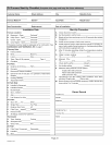
Servicing the Oil Burner
The nozzle and oil filter must be checked before each heat-
ing season. Also, recheck the conditions shown in the Oil
Furnace Start-up Checklist (see page 24),
NOTE - Close the oil line shutoff valve if the burner is shut
down for an extended period of time,
CAUTION
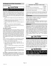
Servicing the Air Filter
NOTE -Under no circumstances should the access panels
to the blower compartment be left off or left partially open,
Throw-Away Type Filters--Check filters monthly and re-
place when necessary to assure proper furnace operation,
Replace filters with like kind and size filters,
Reusable Type Filters--Filters should be checked
monthly and cleaned when necessary to assure proper fur-
nace operation.
Servicing the Blower
Blower motor is prelubricated and sealed for extended op-
eration. No further lubrication is required. Disconnect pow-
er to unit before cleaning blower wheel for debris,
Inspecting the Flue Pipe
The flue pipe should be inspected annually by a qualified
service technician, Remove and clean any soot or ash
found in the flue pipe. Inspect pipe for holes or rusted
areas, If replacement is necessary, replace with the same
size and type as required by code. Inspect the flue draft
control device and replace if found defective.
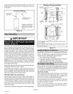
Cleaning the Heat Exchanger
1, Remove the vent pipe from the furnace,
2, Remove the locking screws and the caps from the
clean out tubes, Remove flue access elbow.
3. Using a long spiral wire brush, sweep down the outer
drum of the heat exchanger. Then using the hose at-
tachment, vacuum out loose debris,
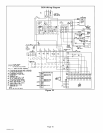
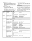
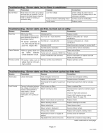
1, Action: Thermostat calls for heat (W terminal is en-
ergized)
Response:
• Blower control board closes oil primary control
T-3T connections,
• After a 15-second pre-purge period, power is sent
to the burner and ignition is established. When the
burner pump reaches full speed, the solenoid
valve is energized.
• Ignition system and oil primary control start the
furnace. Oil flows as long as oil primary control
senses flame.
• Burner motor energized and heat fan on ramp tim-
ing begins. When timing is complete, the circulat-
ing fan isat heat speed and warm air is delivered to
the controlled space.
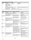
2, Action: Thermostat ends call for heat (W terminal
is de-energized)
Response:
• Oil primary control is de-energized, terminating
the burner cycle.
• Heat fan off ramp timing begins. When timing is
complete, circulating fan is de-energized.
• Blower control board returns to standby mode (oil
primary control and circulating fan are off).
• After the thermostat is satisfied, the thermostat
circuit opens. The solenoid valve is de-energized
before the pump rotation stops. Power to the burn-
er is interrupted, shutting down the burner,
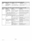
3, Action: Burner fails to light
Response:
• Oil primary control locks out within lockout timing
(timing depends on oil primary control),
• Burner motor is de-energized,
505082M 10_5
Page 18