


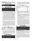
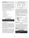
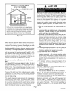
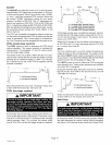

Equipment in Confined Space
All Air From Outside
OR_ _ OIL VENT
_ WATER
IIII IIIIHEATER
II II OILFURNACE
INLET AIR
NOTE - Each air duct opening shall have a free area of at least
one square inch (6A square centimeters) per 2,000 Btu (586 W)
per hour of the total input rating of all equipment in the enclosure. If
the equipment room is located against an outside wall and the air
openings communicate directly with the outdoors, each opening
shall have a free area of at least one square inch (6.4 square
centimeters) per4,000 Btu (1172 W) per hour of the total input
rating of all other equipment in the enclosure.
Figure 12
When ducts are used, they shall be of the same cross-sec-
tional area as the free area of the openings to which they
connect, The minimum dimension of rectangular air ducts
shall be no less than 3" (76 mm), In calculating free area,
the blocking effect of louvers, grilles, or screens must be
considered. If the design and free area of protective cover-
ing is not known for calculating the size opening required, it
may be assumed that wood louvers will have 20 to 25%
free area and metal louvers and grilles will have 60 to 75%
free area, Louvers and grilles must be fixed in the open
position or interlocked with the equipment so that they are
opened automatically during equipment operation,
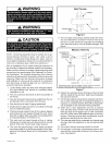
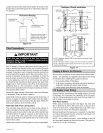
Direct Connection of Outdoor Air for Combus-
tion
The Beckett AFII burner was designed to allow for direct
air intake piping (4" [102 mm]), The maximum equivalent
length of pipe is 70 feet (21.3 m). A 90 ° elbow equals
6feet (1.8 m). The enclosed intake pipe ring may be used
to facilitate direct air intake to the burner through the right
side of the cabinet,
To convert the AFII burner from confined space to outside
combustion air, simply remove the three screws attaching
the inlet air scoop to the burner and insert 4" (102 mm) di-
rect air intake piping.
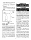
The use of a barometric relief placed in the intake pipe is
recommended when outdoor combustion air is directly
connected to the burner. This will allow confined space air
to be used as combustion air in the event that the opening
to the outdoor air becomes blocked. Using a barometric re-
lief in the intake will reduce the chance of sooting.
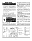
CAUTION
Removal of Unit from Common Venting System
In the event that an existing furnace is removed from a
venting system commonly run with separate appliances,
the venting system is likely to be too large to properly vent
the remaining attached appliances. The following test
should be conducted while each appliance is in operation
and the other appliances not in operation remain con-
nected to the common venting system. If venting system
has been installed improperly, the system must be cor-
rected as outlined in the previous section.
1. Seal any unused openings in the common venting sys-
tem.
2. Visually inspect venting system for proper size and
horizontal pitch and determine there is no blockage or
restriction, leakage, corrosion or other deficiencies
which could cause an unsafe condition.
3. Insofar as is practical, close all building doors and win-
dows and all doors between the space in which the ap-
pliances remaining connected to the common venting
system are located and other spaces of the building.
Turn on clothes dryers and any appliances not con-
nected to the common venting system. Turn on any
exhaust fans, such as range hoods and bathroom ex-
hausts, so they will operate at maximum speed. Do not
operate a summer exhaust fan. Close fireplace damp-
ers.
4. Following the lighting instruction on the unit, place the
appliance being inspected in operation. Adjust ther-
mostat so appliance will operate continuously.
5. Test for spillage using a draft gauge.
6. After it has been determined that each appliance re-
maining connected to the common venting system
properly vents when tested as outlined above, return
doors, windows, exhaust fans, fireplace dampers and
any other fuel burning appliance to their previous con-
dition of use.
7. If improper venting is observed during any of the
above tests, the common venting system must be cor-
rected.
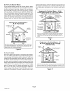
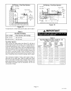
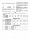
Horizontal Venting
The O23V is approved for horizontal venting with the fol-
lowing mechanical vent systems:
• Tjernlund (sideshot) #SSlC
• Field Controls #SWG-5 with the CK-61 control kit
Refer to the manufacturers' installation instructions for
installation procedures and service parts information.
Do not use the same vent with any other appliance when
using a sidewall vent system.
Maximum permissible vent length is 70 equivalent feet.
Minimum length is 15 equivalent feet. Calculate the equiv-
alent vent pipe footage from the furnace to the mechanical
vent system (Tjernlund or Field Controls) by adding the
straight vent pipe length and the equivalent elbow lengths
together.
Page 9
O23V SERIES